Preamplifiers for Infrared Detectors
- Technology
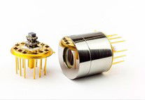
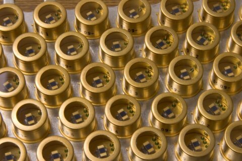
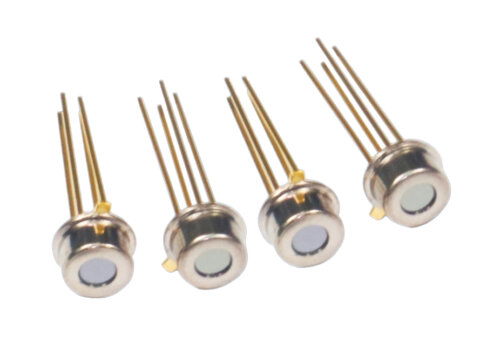
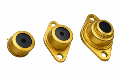
- Infrared photodetectors
- Partner
- Infrared Associates
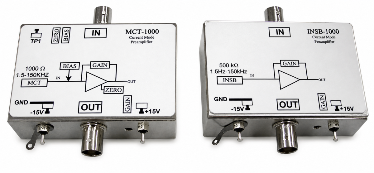
These preamplifiers are specifically developed for use with mid-infrared photodetectors, including photoconductive mercury cadmium telluride (MCT) and photovoltaic indium antimonide (InSb) sensors. Each unit is engineered to maximise the signal quality from its respective detector type – the MCT-1000 models serve HgCdTe MCT detectors requiring a bias voltage, while the InSb-1000 models are tailored to zero-bias InSb photodiodes. By integrating the proper bias supply (for MCT types) and transimpedance amplification stage, the amplifiers eliminate the need for external biasing resistors or complex front-end circuitry. Users benefit from a very low input noise floor and adjustable gain, allowing even very weak IR signals or fast transient events to be amplified for analysis. Typical applications include infrared spectroscopy (e.g. FTIR systems), gas and flame analysis, thermal imaging sensors, and scientific research instruments – anywhere an IR detector’s tiny signal must be faithfully amplified. With a standard ±15 V DC power input and convenient BNC connections, these preamplifiers are easy to integrate into lab setups or OEM equipment, delivering stable and reproducible performance in demanding IR measurement tasks.
Range features
A high level overview of what this range offers
- Low noise performance – Designed for extremely low input noise (on the order of 1.5 nV/√Hz), which helps preserve weak infrared detector signals and improve overall measurement sensitivity.
- High adjustable gain – Offers a wide adjustable gain range (approximately 50× up to 1000× for MCT units, and 5× up to 100× for InSb units) so users can amplify signals to the desired level without saturation. This flexibility allows optimisation of output amplitude for different detector outputs or experimental conditions.
- Integrated bias supply (MCT series) – The MCT-1000 models include an internal constant-voltage bias source adjustable from 0 V to ~+2.5 V. This provides the required bias for photoconductive MCT detectors, eliminating the need for external bias circuits and ensuring the detector operates at its optimal point.
- Zero-bias operation (InSb series) – The InSb-1000 models are optimised for photovoltaic indium antimonide detectors, which typically do not require bias. The preamplifier inherently operates at 0 V bias for lowest noise. (Optional configurations to apply a small reverse bias can be supported for specific use cases, such as speeding up detector response, if needed.)
- Wide bandwidth options – Standard models cover a broad frequency bandwidth (from ~1.5 Hz low-end cut-off up to 150–200 kHz, depending on model), suitable for steady-state and modulated IR signals. High-speed (“HS”) versions extend the upper bandwidth to approximately 1 MHz, enabling capture of fast transients and high-frequency signal components from detectors (for example, in pulsed laser measurements or rapid scanning systems).
- Complete detector interface – All necessary interface components (bias network, coupling capacitors, load resistors, etc.) are built in. The detector connects directly via an SMA-to-BNC cable (no extra bias tees or load resistors needed), and the preamp’s low-impedance voltage output can drive oscilloscopes, ADC inputs, or other instrumentation. This plug-and-play design simplifies integration and reduces the chance of improper external wiring affecting signal quality.
- Standard power supply and form factor – Each preamplifier runs on a dual ±15 V DC supply (a common laboratory power rail), drawing only a few hundred milliamps. The modules are typically compact, bench-top or OEM style units with BNC connectors for input and output. This makes them easy to install alongside the detector and interface with existing test equipment, while ensuring stable operation in industrial or laboratory environments.
Principle
The MCT-1000 series has been specifically developed for operation with photoconductive MCT detectors. The low noise and variable adjustment of the gain, combined with a precise, adjustable bias, provide an ideal complement to our MCT detectors.
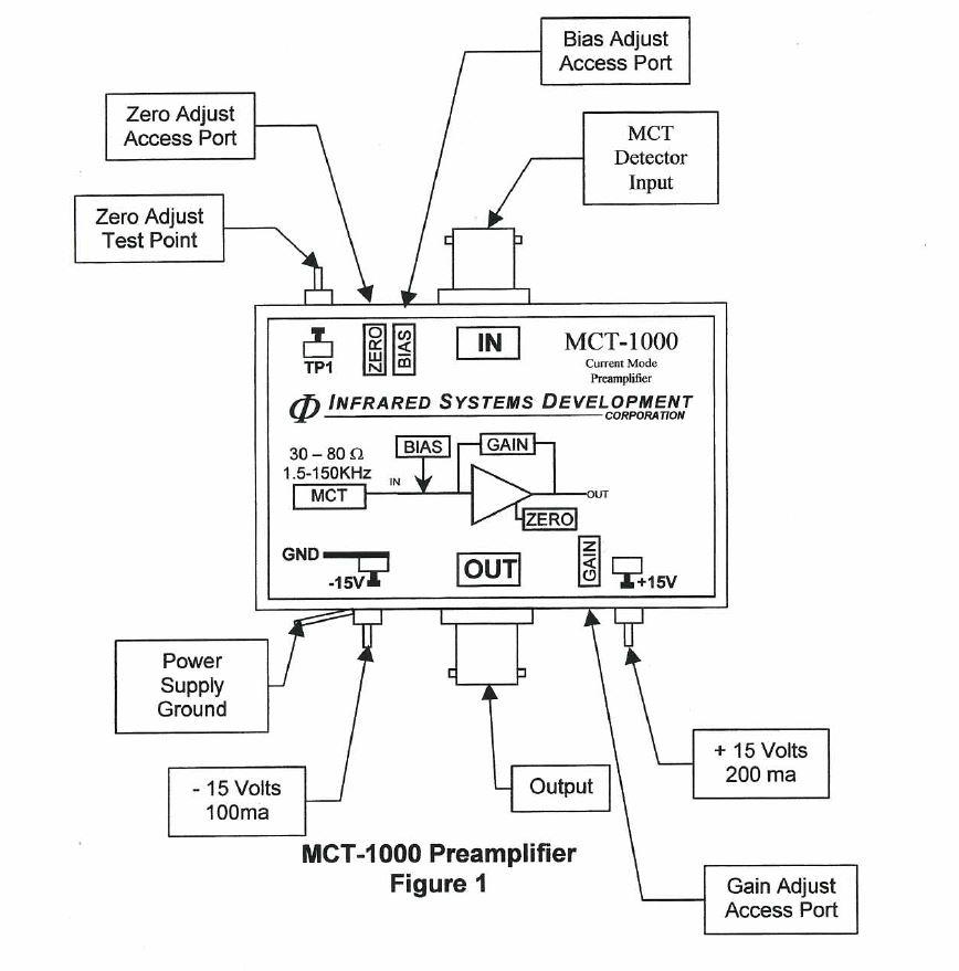
The MCT-1000 preamplifier provides the MCT detector with all the interface circuits required for optimal operation. No external preload or load resistors are required.
The MCT detector is connected to the input BNC connector with an SMA-BNC cable, which is typically supplied with the detector. Positive and negative 15-volt DC power supplies with at least 200mA (+ 15V) and 100mA (-15V) output are required. The detector preload is provided internally, and the preload (or current) is adjustable from typically 0 V to + 2.5 V. The electrical bandwidth is set internally to 1.5Hz to 150kHz. Other bandwidths (up to 1MHz) are available.
An adjustable gain typically delivers variable signal amplitude from 50 to 1000 times. The bias voltage and amplification are affected by the detector impedance, and since all detectors in the resistance are slightly different, there will be a slight variation in the maximum preload and gain.
What’s in this range?
All the variants in the range and a comparison of what they offer
| Specification | MCT-1000 | MCT-1000HS | InSb-1000 | InSb-1000HS |
|---|---|---|---|---|
Detector type / material | Photoconductive MCT (HgCdTe) | Photoconductive MCT (HgCdTe) | Photovoltaic InSb | Photovoltaic InSb |
Detector bias provision | Yes – internal 0 to +2.5 V adjustable bias | Yes – internal 0 to +2.5 V adjustable bias | Not required (0 V, no bias needed) | Not required (0 V default) |
Bandwidth (AC coupled) | ~1.5 Hz to 150 kHz (standard) | ~500 Hz to 1.0 MHz (high-speed) | ~1.5 Hz to 200 kHz (standard) | ~500 Hz to 1.0 MHz (high-speed) |
Gain (adjustable range) | 50× to 1000× | 50× to 1000× | 5× to 100× | 0.5× to 30× |
Power supply requirement | ±15 V DC (approx +15 V @ 200 mA, –15 V @ 100 mA) | ±15 V DC (approx +15 V @ 200 mA, –15 V @ 100 mA) | ±15 V DC (approx +15 V @ 100 mA, –15 V @ 100 mA) | ±15 V DC (approx +15 V @ 100 mA, –15 V @ 100 mA) |
Note: “HS” models denote high-speed variants with extended bandwidth. The gain range for the InSb-1000HS can vary based on the detector’s active area (larger photovoltaic detectors may necessitate lower gain). All models feature DC-coupled variants (e.g. -DC suffix) if true DC response is required.
FAQs
for Preamplifiers for Infrared Detectors
The difference lies in the type of infrared detector each is designed for. MCT-1000 models are intended for photoconductive HgCdTe (MCT) detectors, which require an external bias voltage to operate. These preamps include an internal adjustable bias supply and are optimised to work with the higher impedance and bias needs of MCT detectors. InSb-1000 models, on the other hand, are made for photovoltaic indium antimonide (InSb) detectors, which generate a signal without needing bias. The InSb preamps act as low-noise transimpedance amplifiers for the photodiode current, operating at zero bias (unless a bias is optionally applied for special cases). In short, choose an MCT-1000 series preamp if you are using an MCT photoconductor, or an InSb-1000 series if you have an InSb photodiode – each will correctly match the detector’s operating requirements.
The HS versions (MCT-1000HS and InSb-1000HS) are designed with an extended bandwidth for applications that involve fast-varying or high-frequency IR signals. While the standard preamplifiers handle frequencies up to roughly 150–200 kHz, the HS models can amplify signals up to around 1 MHz. You would use the high-speed version if your measurement involves rapid transients or high modulation rates – for example, pulsed laser detection, fast thermal events, or modulated signals where the standard bandwidth would limit the response. If your application is measuring steady or relatively slow signals, the regular MCT-1000 or InSb-1000 will suffice; but for capturing fast signals without distortion, the HS variant is recommended. Keep in mind that in high-speed configurations, the lower cutoff frequency is around 500 Hz (AC-coupled), so very slow changes or DC signals would be filtered out (see the next question on DC coupling).
Each preamplifier allows you to adjust the signal gain within a certain range to accommodate different detector signal strengths. For the MCT-1000 series, the gain is typically adjustable from about 50× up to 1000× (i.e. it can amplify the detector’s signal 50 to 1000-fold). The InSb-1000 series has a gain range roughly from 5× up to 100×. The adjustment is usually done via a multi-turn potentiometer or dial on the unit – you would turn this knob to increase or decrease the amplification factor as needed. In practice, you’d set the gain so that your detector’s output signal is amplified enough for a clear reading but not so high that it saturates your downstream electronics. The HS versions share similar gain adjustment ranges, although in some cases the effective usable gain might depend on the detector’s characteristics (for example, very large-area photodiodes might require using the lower end of the gain range to maintain stability). In short, you have fine control over gain: simply tweak the built-in adjuster on the preamp until the output signal level is suitable for your needs.
The standard configuration of these preamplifiers is AC-coupled, meaning they have a capacitor at the input that filters out true DC and very low-frequency components. In the default models, the low-frequency cutoff is around 1–1.5 Hz (for MCT-1000 and InSb-1000), which is almost DC – slow changes on the order of several seconds can pass, but a completely steady DC level will not be amplified (it will be blocked by the coupling capacitor). The high-speed variants have a slightly higher low-frequency cutoff around 500 Hz, since pushing the bandwidth to the MHz range requires AC coupling at a few hundred hertz. If you need to amplify DC signals or extremely slow drifts (for instance, if you want the preamp to also pass the constant baseline level from the detector), there are DC-coupled versions available (denoted by “-DC” in the model name, like MCT-1000DC or InSb-1000DC). Those special versions remove or bypass the input capacitor to allow true DC response. In summary, the off-the-shelf units are AC-coupled (good for most applications where you care about changes in signal), but DC-coupled options can be provided if your application demands detection of absolute DC levels from the detector.
The preamplifiers output a voltage signal that represents the amplified detector signal. This output is typically provided on a standard connector (often a BNC output jack on the unit). The output stage of the preamp is designed to drive typical instrument inputs – in other words, you can directly connect the output to an oscilloscope, a spectrum analyzer, a data acquisition (DAQ) card, or other measurement electronics. The output impedance is low enough that it can drive 50 Ω or 1 MΩ inputs without issue, ensuring you get the full bandwidth and signal fidelity. To use it, you simply run a BNC cable from the preamp’s output into your recording or monitoring device. The signal will be an AC-coupled voltage proportional to the detector’s photocurrent (with the gain you’ve set). No additional amplification is usually needed. Just make sure that the input range of your DAQ or scope can accommodate the voltage swing of the preamp’s output (for example, if you have set a high gain and the detector sees a strong signal, the output might swing a few volts). In summary, the output is a ready-to-use analog voltage that you hook up like any other sensor output – the preamp takes care of making it strong and noise-free enough for you to measure directly.
Yes, the manufacturer provides some flexibility through different model variants and can often tailor the preamplifier to specific needs. For example, as mentioned above, DC-coupled versions (with 0 Hz low-end response) are available if you need to pass DC signals. Likewise, the internal bandwidth can sometimes be adjusted or extended – the standard upper cutoff can be modified (up to about 5 MHz in some cases) on request, if your application requires even faster response than the HS version. Additionally, the gain range or bias range could potentially be tweaked or a fixed gain can be set at factory if you require a special calibration. Another offered configuration is a “reverse bias” mode for InSb detectors, where the InSb-1000 preamp can be built to apply a small reverse bias to the photodiode to reduce its capacitance and thus increase speed (useful for certain high-frequency scenarios). Generally, it’s a good idea to discuss your exact requirements with the supplier – they often have a lineup of variants (as reflected by model suffixes like DC, H, HS, etc.) and can advise or provide a custom-tailored unit if needed. The design of these preamps is modular enough that accommodating special customer requirements (within limits) is feasible.
The preamplifiers are designed to add very minimal noise to the detector’s signal, meaning you can detect extremely small signals limited largely by the detector’s own noise. In quantitative terms, the MCT-1000 preamp has an input noise spectral density on the order of 10^-9 volts per √Hz (approximately <1.5 nV/√Hz at 1 kHz), which is extremely low. For practical purposes, this means the preamp itself introduces negligible noise compared to the typical noise of an IR detector (especially in the mid-IR where detectors have thermal noise). In the InSb-1000 preamp, the design is such that it’s often “detector noise limited” – the amplifier is so quiet that the dominant noise source is the InSb photodiode and not the electronics. In short, these preamps allow you to resolve very weak photocurrent signals. The smallest signal you can detect will depend on the detector’s characteristics and the measurement bandwidth, but the electronics will not be the limiting factor in most cases. For instance, if your detector can only produce, say, a few nanoamperes of signal above noise, the preamp (with high gain and low noise) can amplify that into millivolt-level outputs that you can measure on a scope. Overall, you can trust that these amplifiers will not swamp your signal with noise – they are purpose-built for precision IR detection tasks, letting you take full advantage of your detector’s sensitivity.