CT-0155NSR-Mx2L-A 1310 nm LED 2 km 155 Mb/s SFF Transceiver
- Technology
- Optical transceivers
- Partner
- Coretek
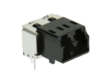
The CT-0155NSR-Mx2L-A provides optical-to-electrical and electrical-to-optical conversion for short-reach multimode fibre links. Its 100 to 155 Mb/s NRZ data range supports 100Base-FX Fast Ethernet, FDDI, ATM/SONET OC-3 and SDH STM-1 applications. A nominal 1310 nm LED transmitter and duplex LC receptacle provide the optical interface, while the MSA-compatible 2×5 SFF footprint supports board-level integration. The transceiver operates from a single 3.3 V supply and uses differential PECL transmit and receive data interfaces. Two variants allow the signal-detect output to be matched to either PECL or TTL host logic. Its −40 to +85 °C ambient operating range accommodates equipment exposed to extended temperatures. The construction is RoHS-compliant and lead-free, with an optical interface designed to meet Class 1 requirements under EN 60825-1.
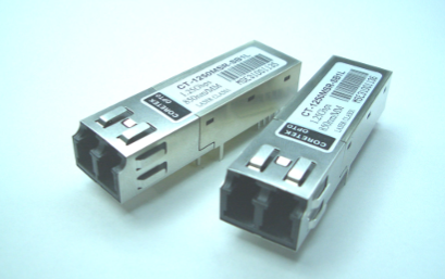
Range features
A high level overview of what this range offers
- 100 to 155 Mb/s NRZ operation: Covers Fast Ethernet, FDDI and 155 Mb/s OC-3 or STM-1 links.
- Up to 2 km multimode reach: Supports short-reach fibre connections between network and communications equipment.
- 1310 nm LED transmitter: Provides a defined optical interface for multimode fibre applications.
- Duplex LC receptacle: Uses separate transmit and receive fibre paths in a compact connector format.
- 2×5 SFF footprint: Supports integration into boards designed around the SFF multi-source agreement.
- Single 3.3 V supply: Simplifies connection to 3.3 V host systems.
- Differential PECL data interface: Supports high-speed transmit and receive signalling.
- PECL or TTL signal-detect variants: Allows the status output to be matched to the host logic family.
- −40 to +85 °C operation: Accommodates equipment operating across an extended ambient temperature range.
- Transmit-disable input: Gives the host system electrical control of the optical transmitter.
- Class 1 optical design: Supports integration where EN 60825-1 eye-safety requirements apply.
- RoHS-compliant, lead-free construction: Supports restricted-substance requirements for electronic assemblies.
Downloads
for CT-0155NSR-Mx2L-A 1310 nm LED 2 km 155 Mb/s SFF Transceiver
What’s in this range?
All the variants in the range and a comparison of what they offer
Technical specifications
| Category | Parameter | Symbol | Minimum | Typical | Maximum | Unit or standard | Notes |
|---|---|---|---|---|---|---|---|
General | Data rate | — | 100 | — | 155 | Mb/s | NRZ signalling |
General | Rated link distance | — | — | — | 2 | km | Multimode fibre link |
General | Nominal transmitter wavelength | — | — | 1310 | — | nm | LED transmitter |
General | Optical connector | — | — | Duplex LC | — | — | Separate transmit and receive paths |
General | Form factor | — | — | 2×5 SFF | — | MSA | Board-mounted footprint |
General | Electrical data interface | — | — | Differential PECL | — | — | Transmit and receive data |
General | Optical safety | — | — | Class 1 design | — | EN 60825-1 | Eye-safety design target |
General | Construction | — | — | RoHS-compliant and lead-free | — | — | Restricted-substance construction |
Absolute maximum | Storage temperature | TS | −40 | — | 85 | °C | — |
Absolute maximum | Supply voltage | VCC | 0 | — | 6 | V | — |
Absolute maximum | Lead soldering temperature | TSOLD | — | — | 260 | °C | Maximum 10 seconds on the lead |
Absolute maximum | Data input voltage | — | 0 | — | VCC | V | — |
Operating condition | Ambient operating temperature | TA | −40 | — | 85 | °C | — |
Operating condition | Supply voltage | VCC | 3.1 | — | 3.5 | V | Nominal 3.3 V supply |
Electrical | Transmitter supply current | ICCT | — | — | 140 | mA | — |
Electrical | TTL transmit-disable input, low | VIL | — | — | 0.8 | V | — |
Electrical | TTL transmit-disable input, high | VIH | VCC−1.3 | — | VCC | V | — |
Electrical | Receiver supply current | ICCR | — | — | 100 | mA | — |
Electrical | Receiver data output, low | VOL−VCC | −1.810 | — | −1.620 | V | Compatible with 10K, 10KH, 100K ECL and PECL inputs |
Electrical | Receiver data output, high | VOH−VCC | −1.025 | — | −0.880 | V | Compatible with 10K, 10KH, 100K ECL and PECL inputs |
Electrical | PECL signal-detect output, low | VOL−VCC | −1.810 | — | −1.620 | V | — |
Electrical | PECL signal-detect output, high | VOH−VCC | −1.025 | — | −0.880 | V | — |
Electrical | TTL signal-detect output, low | VOL | — | — | 0.4 | V | — |
Electrical | TTL signal-detect output, high | VOH | 2.4 | — | — | V | — |
Transmitter | Average optical output power | PO | −19 | −17 | −14 | dBm | Measured into 62.5/125 µm, 0.275 NA graded-index multimode fibre |
Transmitter | Extinction ratio | ER | 8.2 | — | — | dB | — |
Transmitter | Centre wavelength | λc | 1270 | — | 1360 | nm | Nominal wavelength 1310 nm |
Transmitter | RMS spectral width | Δλ | — | — | 200 | nm | — |
Transmitter | Optical rise time, 10–90% | tr | 0.6 | — | 3.0 | ns p-p | — |
Transmitter | Optical fall time, 10–90% | tf | 0.6 | — | 3.0 | ns p-p | — |
Transmitter | Output eye | — | — | Compliant | — | ITU-T G.957 | — |
Receiver | Maximum input optical power | Pmax | — | — | −14 | dBm | Measured using a 2²³−1 PRBS at BER below 10⁻¹⁰ |
Receiver | Receiver sensitivity | Pmin | — | — | −32 | dBm | Measured using a 2²³−1 PRBS at BER below 10⁻¹⁰ |
Receiver | Operating wavelength | λ | 1100 | — | 1600 | nm | — |
Receiver | Signal-detect asserted threshold | PA | — | — | −32 | dBm | Low-to-high transition |
Receiver | Signal-detect deasserted threshold | PD | −47 | — | — | dBm | High-to-low transition |
Receiver | Signal-detect hysteresis | PA−PD | 0.5 | — | 4 | dB | — |
Variant comparison
| Specification | Variant 1 | Variant 2 |
|---|---|---|
Model number | CT-0155NSR-M22L-A | CT-0155NSR-ME2L-A |
Listed electrical designation | 3.3 V PECL DC/DC | 3.3 V TTL DC/DC |
Signal-detect output | PECL | TTL |
Maximum link distance | 2 km | 2 km |
Nominal wavelength | 1310 nm | 1310 nm |
Optical output power | −19 to −14 dBm | −19 to −14 dBm |
Receiver sensitivity | ≤ −32 dBm | ≤ −32 dBm |
Pin assignment
| Pin or connection | Symbol | Function |
|---|---|---|
Mounting posts | — | Mechanical board attachment; do not connect to circuit ground, although connection to chassis ground is permitted |
1 | VEER | Receiver signal ground |
2 | VCCR | Receiver power supply |
3 | SD | PECL or TTL signal-detect output; a high level indicates a received optical signal |
4 | RD− | Inverted differential receiver data output |
5 | RD+ | Non-inverted differential receiver data output |
6 | VCCT | Transmitter power supply |
7 | VEET | Transmitter signal ground |
8 | TXDIS | Transmitter-disable input |
9 | TD+ | Non-inverted differential transmitter data input |
10 | TD− | Inverted differential transmitter data input |
Recommended interface arrangements are provided for both the 3.3 V PECL and 3.3 V TTL signal-detect variants. Mechanical dimensions, host-board layout and circuit component details are supplied as drawings in the technical specification.
FAQs
for CT-0155NSR-Mx2L-A 1310 nm LED 2 km 155 Mb/s SFF Transceiver
Yes, provided the host interface and optical link meet its stated operating conditions. The transceiver accepts 100 to 155 Mb/s NRZ data and is intended for 100Base-FX, FDDI, ATM/SONET OC-3 and SDH STM-1 applications. This range covers both 100 Mb/s Ethernet-class links and 155 Mb/s telecommunications interfaces without changing the optical module. Its 2 km figure is a short-reach multimode rating rather than a guarantee for every fibre installation. The link design must still account for fibre attenuation, connectors, splices, temperature, ageing and the required system margin.
The worst-case receive-power budget is 13 dB, calculated from the minimum transmitter output of −19 dBm and the receiver sensitivity limit of −32 dBm. This figure is available before allowing for engineering margin, fibre loss, LC connector loss, splices, contamination, temperature variation and component ageing. The maximum receiver input is −14 dBm, which is equal to the strongest specified transmitter output. Designers should therefore verify both the low-power sensitivity corner and the high-power overload corner, particularly for very short fibre runs. Final link acceptance should be based on measured receive power across the intended operating temperature range.
Select the CT-0155NSR-M22L-A when the host requires a PECL signal-detect output and the CT-0155NSR-ME2L-A when a TTL status output is required. Both variants use a 3.3 V supply and share the same stated optical performance, link distance and connector arrangement. The main transmit and receive data paths remain differential PECL, so the variant choice relates to signal detect rather than the communication protocol. The PECL status levels are referenced to VCC, while the TTL version specifies a maximum low level of 0.4 V and a minimum high level of 2.4 V. Host logic compatibility and termination should be confirmed before the board layout is finalised.
Allow for a maximum transmitter current of 140 mA and a maximum receiver current of 100 mA. If both sections reach their stated limits simultaneously, the combined current allowance is 240 mA. At the maximum operating supply of 3.5 V, this corresponds to an upper-bound electrical input estimate of approximately 0.84 W, although it is not a specified thermal-dissipation figure. The transmitter and receiver supply pins should be locally decoupled, with short return paths to their respective signal grounds. Board-level thermal assessment should ensure that the module remains within its −40 to +85 °C ambient operating range under the intended enclosure and airflow conditions.
The transceiver is intended for multimode fibre and uses a duplex LC receptacle, with separate fibres for transmitting and receiving data. Average optical output power is characterised with 62.5/125 µm, 0.275 NA graded-index multimode fibre. The LED has a nominal wavelength of 1310 nm, with the transmitter centre wavelength specified from 1270 to 1360 nm and the receiver operating range from 1100 to 1600 nm. These figures define optical compatibility but do not remove the need to validate the installed fibre type and link loss. Correct duplex polarity, connector cleanliness and controlled bend radius are important for maintaining the expected receive-power margin.
The signal-detect output indicates whether the receiver has recognised an optical input, with a high output representing a received signal. The asserted threshold is bounded at −32 dBm, while the deasserted threshold is bounded at −47 dBm. These values are limit conditions rather than fixed switching points that imply a constant 15 dB difference. The specified signal-detect hysteresis is 0.5 to 4 dB, helping to prevent repeated output switching when received power is close to the decision level. Signal detect is suitable for link-status and fault-handling functions, but it should not be treated as a calibrated optical power measurement.
The interface uses separate transmitter and receiver supply and ground connections, together with differential transmit and receive data pairs. Pins 9 and 10 form the TD+ and TD− transmitter input pair, while pins 5 and 4 provide the RD+ and RD− receiver output pair. Pin 8 controls transmitter disable, and pin 3 supplies the PECL or TTL signal-detect output selected by the product variant. The mounting posts are intended for mechanical attachment and should not be connected to circuit ground, although chassis-ground connection is permitted. Differential routes should be kept short and matched, with suitable high-speed termination and local supply filtering.
The permitted ambient operating range is −40 to +85 °C, and the storage temperature range uses the same limits. Normal operation requires a supply between 3.1 and 3.5 V, while the absolute maximum supply rating is 0 to 6 V. Lead soldering is limited to 260 °C for no more than 10 seconds on the lead, so the assembly process must avoid longer exposure at that temperature. The optical interface is designed to meet Class 1 eye-safety requirements under EN 60825-1, and the construction is RoHS-compliant and lead-free. Complete equipment compliance still depends on the host design, enclosure, power system and final EMC testing.