PLMW3 1310 nm 5 mW 3 GHz Coaxial Analogue DFB Laser (Wireless)
- Technology
- Analogue - RF over fibre - components
- Partner
- AGx Technologies
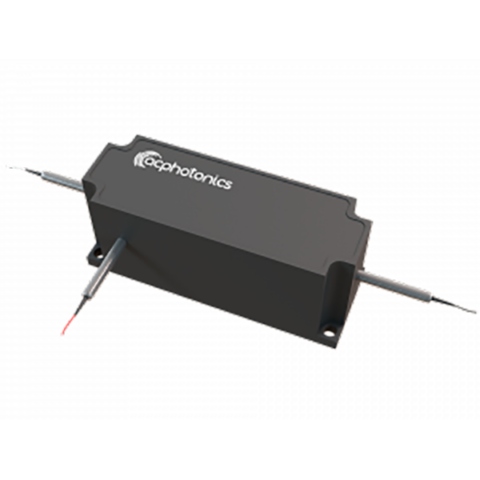
The PLMW3 1310 nm DFB coaxial laser is designed as a directly modulated optical source for analogue wireless and RF-over-fibre transmission. It combines an MQW distributed feedback laser with a hermetically sealed coaxial package and a single-mode fibre pigtail. Its minimum 3 GHz bandwidth makes it suitable for CDMA, WCDMA and related RF signal transport applications. An internal monitor photodiode provides the feedback signal required for automatic optical power control. Single- and double-isolator configurations allow the optical isolation level to be selected according to the reflection characteristics of the link. The uncooled operating range extends from -20 °C to 85 °C, supporting installations exposed to changing equipment temperatures. SC/APC and FC/APC connector options are available on a minimum one-metre SMF-28e fibre pigtail. The PLMW3 ordering scheme defines guaranteed output-power options from at least 1 mW to at least 4 mW; a separate 5 mW order code is not defined.
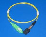
Range features
A high level overview of what this range offers
- 1310 nm MQW DFB emitter: Supports single-mode analogue optical transmission over RF-over-fibre links.
- Minimum 3 GHz bandwidth: Accommodates broadband RF modulation within the specified operating range.
- RIN no higher than -145 dB/Hz: Helps control the laser’s intensity-noise contribution to the link.
- IMD3 no higher than -60 dBc under stated test conditions: Provides a defined third-order distortion limit for analogue link planning.
- Single or double optical isolator: Provides minimum isolation of 30 dB or 43 dB at 25 °C.
- Internal monitor photodiode: Enables closed-loop optical power monitoring and control.
- Hermetically sealed coaxial package: Protects the laser assembly while providing a standard integration format.
- -20 °C to 85 °C operating range: Supports uncooled operation across changing equipment temperatures.
- SC/APC or FC/APC termination: Allows the optical interface to be matched to the intended installation.
- Optional mounting clamp: Adds a mechanical installation option through the
-Corder suffix. - RoHS compliant: Supports integration into equipment subject to applicable restricted-substance requirements.
Downloads
for PLMW3 1310 nm 5 mW 3 GHz Coaxial Analogue DFB Laser (Wireless)
What’s in this range?
All the variants in the range and a comparison of what they offer
Electro-optical characteristics
| Parameter | Symbol | Conditions | Minimum | Maximum | Unit |
|---|---|---|---|---|---|
Threshold current | Ith | 25 °C | — | 15 | mA |
Threshold current | Ith | 85 °C | — | 40 | mA |
Operating temperature | Top | — | -20 | 85 | °C |
Operating current | Iop | 25 °C | — | 90 | mA |
Operating voltage | Vop | 25 °C | — | 2.1 | V |
Monitor photodiode responsivity | rMPD | — | 10 | 400 | µA/mW |
Monitor photodiode dark current | ID | Iop = 0 mA | — | 0.2 | µA |
Operating wavelength | λOP | IF = IOP, T = TOP | 1300 | 1320 | nm |
Side-mode suppression ratio | SMSR | IF = IOP | 30 | — | dB |
Optical isolation, single isolator | ISO | 25 °C | 30 | — | dB |
Optical isolation, double isolator | ISO | 25 °C | 43 | — | dB |
Tracking error | ER | — | -1 | +1 | dB |
Bandwidth | — | — | 3 | — | GHz |
Second-order intermodulation | IMD2 | Rated power, 25 °C, 10% OMI; two-tone test at 936 MHz and 958 MHz | — | — | dBc |
Third-order intermodulation | IMD3 | Rated power, 25 °C, 10% OMI; two-tone test at 936 MHz and 958 MHz | — | -60 | dBc |
Relative intensity noise | RIN | — | — | -145 | dB/Hz |
Ordering scheme
| Segment | Function | Available options |
|---|---|---|
PLMW3 | Product series | Fixed identifier |
A | Pin configuration | Type A |
N | Optical isolator | 1 = single; 2 = double |
y | Minimum output power | 1 = ≥1 mW; 2 = ≥2 mW; 3 = ≥3 mW; 4 = ≥4 mW |
z | Optical connector | S = SC/APC; F = FC/APC |
C | Mounting option | Optional mounting clamp |
Order-code format: PLMW3-A-N-y-z[-C]
Worked example: PLMW3-A-1-4-S-C specifies the Type A configuration with a single isolator, an output of at least 4 mW, an SC/APC connector and the optional mounting clamp.
Output-power clarification: The order code defines options from at least 1 mW to at least 4 mW. It does not identify a separate 5 mW variant.
Maximum ratings at 25 °C
| Parameter | Conditions | Minimum | Maximum | Unit |
|---|---|---|---|---|
Storage temperature | Continuous | -40 | 85 | °C |
Photodiode reverse voltage | 60 seconds | — | 15 | V |
Photodiode reverse voltage | Continuous | — | 10 | V |
Forward DC laser current | Continuous | — | 100 | mA |
Reverse DC laser voltage | Continuous | — | 1 | V |
Lead soldering temperature | 10 seconds | — | 260 | °C |
Pin configuration
| Pin | Type A connection |
|---|---|
1 | PD+ |
2/GND | LD+ |
3 | LD- |
4 | PD- |
Mechanical and optical interface
- Hermetically sealed, industry-standard coaxial package.
- SMF-28e single-mode optical fibre with flame-retardant Hytrel coating.
- Fibre outer diameter: 0.9 mm.
- Minimum fibre length: 1 metre.
- SC/APC and FC/APC connector terminations available.
- Optional mounting clamp selected by adding
-Cto the order code.
FAQs
for PLMW3 1310 nm 5 mW 3 GHz Coaxial Analogue DFB Laser (Wireless)
A dedicated 5 mW order code is not defined in the PLMW3 ordering structure. The output-power digit provides four options: at least 1 mW, 2 mW, 3 mW or 4 mW. The operating-output specification refers back to these model options rather than giving a separate typical or maximum power. An engineer requiring a guaranteed 5 mW launch level should therefore not treat the range description alone as a confirmed optical rating. The exact part number and guaranteed minimum power should be confirmed before completing link-budget, receiver-overload or laser-safety calculations.
The choice should be based on the optical reflection environment and the isolation margin required by the analogue link. The single-isolator version provides at least 30 dB of optical isolation at 25 °C, while the double-isolator version provides at least 43 dB under the same condition. This gives the double-isolator configuration a 13 dB higher specified minimum isolation level. Greater isolation can be useful in systems containing several connector interfaces, splitters or other components that may return reflected light towards the laser. Final selection should also consider the complete optical path and the linearity performance required under actual installation conditions.
The PLMW3 requires a controlled laser-current driver, normally combined with automatic optical power control using the internal monitor photodiode. Threshold current is specified at no more than 15 mA at 25 °C and 40 mA at 85 °C, while operating current is limited to 90 mA at 25 °C with a maximum operating voltage of 2.1 V. Monitor responsivity ranges from 10 to 400 µA/mW, and dark current is no more than 0.2 µA when laser current is zero. The control circuit therefore needs sufficient gain range and headroom to accommodate device variation. Continuous laser current must remain below the 100 mA absolute maximum rather than using that damage limit as the normal operating point.
The laser has a specified minimum bandwidth of 3 GHz, but that value alone does not define gain flatness or system response across every frequency below 3 GHz. Third-order intermodulation is specified at no more than -60 dBc at rated optical power, 25 °C and 10% optical modulation index. The stated two-tone test uses 936 MHz and 958 MHz, so the result is directly relevant to that particular test arrangement. No numerical second-order intermodulation limit is defined. Systems operating at other carrier frequencies, modulation depths or temperatures should therefore be validated at link level with the intended driver, fibre path and receiver.
Yes, the PLMW3 is intended for uncooled operation from -20 °C to 85 °C. The driver still needs enough compliance and current-control range to account for temperature-dependent behaviour, as the maximum threshold current increases from 15 mA at 25 °C to 40 mA at 85 °C. Operating current should remain within the 90 mA limit at 25 °C and below the 100 mA continuous absolute maximum. Storage is permitted from -40 °C to 85 °C, while lead soldering is limited to 260 °C for 10 seconds. The package is hermetically sealed, but the surrounding assembly still requires suitable environmental and thermal design.
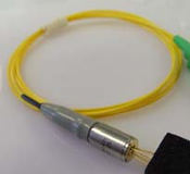
The laser is supplied with an SMF-28e single-mode fibre pigtail using a flame-retardant Hytrel coating and a 0.9 mm outer diameter. The pigtail is at least one metre long and can be terminated with either an SC/APC or FC/APC connector. Optical components in the link should support the complete 1300 to 1320 nm operating wavelength range rather than only a nominal 1310 nm point. APC connectors should be mated with compatible APC interfaces to preserve the intended angled physical contact. For mechanical installation, the optional -C suffix adds a mounting clamp to the selected laser configuration.
The operating wavelength spans 1300 to 1320 nm, with a minimum side-mode suppression ratio of 30 dB and relative intensity noise no higher than -145 dB/Hz. The SMSR figure defines the minimum separation between the principal lasing mode and unwanted side modes, which matters when the optical path includes wavelength-sensitive components. Couplers, splitters, receivers and any wavelength-selective devices should be rated across the full operating interval. RIN affects the noise contribution of the optical transmitter, but its effect on received performance also depends on optical power and receiver bandwidth. Designs using narrow optical filtering should be qualified because no wavelength-temperature coefficient is defined.
The laser is limited to 100 mA continuous forward current and 1 V continuous reverse voltage. The monitor photodiode can withstand up to 10 V reverse bias continuously or 15 V for no more than 60 seconds. These figures are damage limits rather than recommended design set-points, so the driver should include current limiting, controlled start-up and reverse-voltage protection. Assembly processes must also keep lead soldering to no more than 260 °C for 10 seconds. No ESD rating is defined, so the component should be handled using appropriate static-control procedures during storage, assembly and testing.