PLMF3 1310 nm 14 mW 3 GHz Coaxial Analogue DFB Laser (Forward Path)
- Technology
- Analogue - RF over fibre - components
- Partner
- AGx Technologies
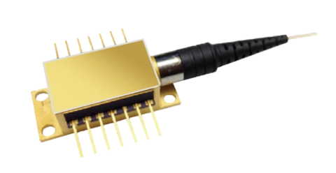
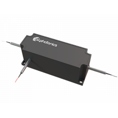
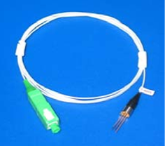
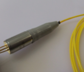
The PLMF3 1310 nm 14 mW analogue DFB laser module is designed for CATV forward-path and RF-over-fibre transmitters. Its MQW DFB emitter is housed in a hermetically sealed coaxial package and coupled to a single-mode fibre pigtail. The selected 14 mW power grade supports optical link-budget planning for intermediate- and long-reach analogue applications. A minimum bandwidth of 2.7 GHz enables use in broadband modulation systems, while the relative intensity noise specification supports noise-sensitive analogue links. An internal optical isolator and monitor photodiode support reflection management and closed-loop bias control. The module is suitable for uncooled use up to 40 °C and can be externally cooled when required by the thermal design. Connector options include SC/APC, FC/APC and an unterminated pigtail, allowing the optical interface to be matched to the transmitter assembly.
Range features
A high level overview of what this range offers
- 1310 nm MQW DFB emitter: Supports analogue transmission over standard single-mode fibre.
- 14 mW optical output grade: Provides a defined power option for optical link-budget calculations.
- Minimum 2.7 GHz bandwidth: Accommodates broadband CATV forward-path and RF-over-fibre modulation.
- Relative intensity noise of no more than -145 dB/Hz: Supports noise management in analogue optical links.
- Minimum 35 dB optical isolation: Helps reduce the influence of reflected optical power on the laser.
- Internal monitor photodiode: Enables optical-power feedback and bias-control functions when used with a suitable circuit.
- Hermetically sealed coaxial package: Provides an established package format for transmitter integration.
- SC/APC, FC/APC or no-connector options: Allow the fibre interface to suit connectorised or spliced assemblies.
- SMF-28 pigtail with flame-retardant Hytrel coating: Provides a single-mode optical connection with at least 1 m of fibre.
- RoHS compliance: Supports equipment designed around RoHS material requirements.
What’s in this range?
All the variants in the range and a comparison of what they offer
Product specifications
| Category | Parameter | Condition or symbol | Specification |
|---|---|---|---|
Product | Device type | — | MQW DFB analogue laser module |
Product | Package | — | Hermetically sealed coaxial package |
Optical | Nominal wavelength | — | 1310 nm |
Optical | Operating wavelength | λOP, IF = IOP | 1290 to 1330 nm |
Optical | Operating output power | Tcase = 25 °C | 14 mW power grade |
Optical | Side-mode suppression ratio | SMSR, IF = IOP | Minimum 32 dB |
Optical | Optical isolation | ISO | Minimum 35 dB |
Optical | Tracking error | ER | -1 to +1 dB |
Optical | Relative intensity noise | RIN | Maximum -145 dB/Hz |
RF performance | Bandwidth | — | Minimum 2.7 GHz |
RF performance | Carrier-to-noise ratio | CNR, stated multichannel test condition | Minimum 51 dB |
RF performance | Composite second-order distortion, grade A | CSO, stated multichannel test condition | Maximum -53 dBc |
RF performance | Composite second-order distortion, grade B | CSO, stated multichannel test condition | Maximum -57 dBc |
RF performance | Composite second-order distortion, grade C | CSO, stated multichannel test condition | Maximum -60 dBc |
RF performance | Composite triple beat | CTB, stated multichannel test condition | Maximum -65 dBc |
Electrical | Threshold current | Tcase = 25 °C | Maximum 15 mA |
Electrical | Threshold current | Tcase = 85 °C | Maximum 40 mA |
Electrical | Operating current | Tcase = 25 °C | Maximum 90 mA |
Electrical | Operating voltage | VOP | Maximum 2.1 V |
Monitor photodiode | Responsivity | rMPD | 50 to 2000 µA |
Monitor photodiode | Dark current | IOP = 0 mA | Maximum 0.2 µA |
Temperature | Operating temperature | IF = IOP | -20 to +85 °C |
Temperature | Uncooled operation guidance | — | Up to 40 °C |
Fibre | Fibre type | — | SMF-28 single-mode optical fibre |
Fibre | Coating | — | Flame-retardant Hytrel |
Fibre | Pigtail length | — | Minimum 1 m |
Fibre | Connector options | — | SC/APC, FC/APC or no connector |
Mechanical | Mounting bracket | — | Optional |
Compliance | Materials compliance | — | RoHS compliant |
Maximum rating | Storage temperature | Continuous | -40 to +85 °C |
Maximum rating | Monitor photodiode reverse voltage | 60 seconds | 15 V |
Maximum rating | Monitor photodiode reverse voltage | Continuous | 10 V |
Maximum rating | Forward DC laser current | Continuous | 120 mA |
Maximum rating | Reverse DC laser voltage | Continuous | 1 V |
The CNR, CSO and CTB figures use a test condition of 79 unmodulated NTSC carriers, 0 dBm received optical power and a case temperature of 25 °C.
Ordering code: For the 14 mW version, the order-code structure is PLMF3-A-1-14-[distortion grade]-[connector code]. Distortion grades are A, B or C. Connector code S denotes SC/APC, F denotes FC/APC and N denotes no connector.
Type A pin allocation
| Pin | Assignment |
|---|---|
1 | Monitor photodiode anode |
2 | Laser diode anode and case ground |
3 | Laser diode cathode |
4 | Monitor photodiode cathode |
FAQs
for PLMF3 1310 nm 14 mW 3 GHz Coaxial Analogue DFB Laser (Forward Path)
For design assurance, treat the module as having a guaranteed minimum bandwidth of 2.7 GHz rather than a guaranteed 3.0 GHz. The 3 GHz description is a rounded range label, whereas 2.7 GHz is the explicit electro-optical characteristic. A design operating close to 3 GHz should therefore include measured margin for the complete transmitter, fibre link and receiver rather than relying on the range name alone. If the required passband extends beyond 2.7 GHz, validate the selected distortion grade and full link response under the intended bias and temperature conditions.
Yes, it is intended for CATV forward-path and RF-over-fibre transmission. The 14 mW grade operates around 1310 nm, with a minimum CNR of 51 dB and CSO limits from -53 to -60 dBc depending on grade; CTB is limited to -65 dBc. These analogue figures use 79 unmodulated NTSC carriers, 0 dBm received optical power and a 25 °C case temperature. Engineers using different channel counts, modulation formats or received powers should treat these values as a defined comparison condition and confirm system-level performance for their channel plan.
The module can be used without active cooling up to 40 °C, while operation beyond that point should be assessed with external temperature control. Its stated operating range is -20 to +85 °C, but threshold current rises from a maximum of 15 mA at 25 °C to 40 mA at 85 °C, showing the effect of temperature on drive requirements. The driver and thermal design must maintain the required operating point without approaching the 90 mA operating-current limit or 120 mA absolute forward-current rating. For outdoor or enclosed transmitters, allow thermal margin for case-to-ambient rise rather than using ambient temperature alone.
Choose grade A, B or C according to the composite second-order distortion target of the optical link. At 25 °C, the CSO limits are -53 dBc for grade A, -57 dBc for grade B and -60 dBc for grade C, while CTB is -65 dBc for all listed grades under the stated multichannel conditions. Because a more negative CSO figure represents lower composite distortion, grade C provides the tighter CSO limit. Selection should still be based on the total transmitter and receiver distortion budget, as the laser grade alone does not determine end-to-end link performance.
Use the internal optical isolator together with an APC connector and a controlled-reflection fibre path. The module provides at least 35 dB of optical isolation, while SC/APC and FC/APC versions provide angled physical-contact interfaces that can support reflection management in the assembled link. The isolator can help reduce sensitivity to returned optical power, but connectors, splices, passive components and receiver interfaces still contribute to overall return loss. Choose S for SC/APC, F for FC/APC or N for no factory-fitted connector, then verify reflections using the complete installed optical path.
The internal monitor photodiode is intended to provide feedback for laser bias or optical-power control. Its response is specified as 50 to 2000 µA, with a maximum dark current of 0.2 µA when the laser operating current is zero; pin 1 is the photodiode anode and pin 4 is its cathode. The control circuit should accommodate this response range and remain within reverse-voltage limits of 10 V continuously or 15 V for 60 seconds. In practice, loop gain, sensing resistance and fault handling must be selected so that start-up and temperature changes do not overdrive the laser.
Select a driver that can supply the required bias below the 90 mA maximum operating-current figure at 25 °C while preserving protection margin to the 120 mA continuous forward-current rating. The laser operating voltage is no more than 2.1 V, threshold current is up to 15 mA at 25 °C and reverse laser voltage must remain below 1 V. These limits call for controlled start-up, current limiting and reverse-voltage protection rather than a simple unprotected current source. The current required by an individual module and operating temperature should be established during transmitter calibration using the monitor photodiode and measured optical output.
The optical interface is an SMF-28 single-mode pigtail with flame-retardant Hytrel coating and a minimum length of 1 m. SC/APC and FC/APC terminations are available, while the no-connector option is suitable when the assembly will be spliced or terminated during manufacture. A mounting bracket is optional, and the electrical connection uses the four-pin Type A layout, so mechanical retention and pin orientation must both be checked in the transmitter design. No minimum bend radius is specified; apply the handling limits associated with the selected SMF-28 cable construction and connector assembly.