RF Triplexers
- Technology
- RF Filters
- Partner
- Sangshin
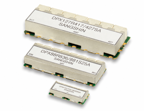
The TPX Series is a range of RF triplexers designed to combine or separate three defined frequency paths. Each variant covers a different group of RF bands, allowing the electrical characteristics to be matched to the intended system architecture. The range is suitable for engineers developing cellular, telecommunications and other multi-band RF equipment. Available passband edges extend from 699 MHz at the lower end to 4200 MHz at the upper end of the range. Several options are aligned with identified bands including 1, 2, 3, 5, 9, 11, 12, 14, 20, 21, 24, 27, 32, 41, 45, 66 and 77. The comparison data include insertion loss, return loss, ripple, rejection-band attenuation and mechanical dimensions. Final design-in should also confirm impedance, power handling, operating temperature and interface requirements, as these parameters are not defined in the available technical data.

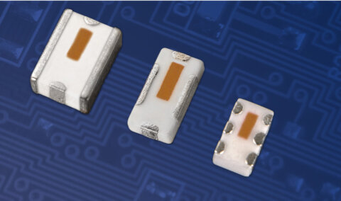
The TPX Series ceramic monoblock RF triplexers are intended for applications that need three defined RF paths within one filtering component. The range covers multiple band groupings for cellular and telecommunications designs, helping engineers compare suitable options by frequency plan, insertion loss, return loss, ripple, attenuation and package size.
Across the listed variants, passband edge coverage extends from 699 MHz to 4200 MHz. Because each model uses a different three-path arrangement, selection should be based on the complete path definitions and the wider RF system requirements rather than frequency labels alone.
Range features
A high level overview of what this range offers
- Three frequency paths – can combine or separate three specified RF bands within one component.
- Ceramic monoblock construction – supports a consolidated filter layout, subject to PCB and interface requirements.
- Eight product variants – provides a choice of frequency combinations for different multi-band systems.
- 699 to 4200 MHz overall edge-frequency coverage – supports selection across low, mid and higher RF frequency ranges.
- Maximum insertion loss from 1.5 to 4.8 dB – provides defined values for RF link-budget calculations.
- Minimum return loss from 14 to 18 dB – supports comparison of in-band matching performance.
- Model-specific attenuation from 10 to 85 dB – helps engineers assess rejection across the listed frequency regions.
- Defined package dimensions – supports preliminary PCB and enclosure planning.
What’s in this range?
All the variants in the range and a comparison of what they offer
| Part No. | Classification | Normalised Technology | Band | Frequency Paths | Start Freq. [MHz] | Center Freq. [MHz] | Stop Freq. [MHz] | Insertion Loss [dB/max.] | Return Loss [dB/min.] | Ripple [dB/max.] | Attenuation [dB/min.] | Dimensions (L × W × H) [mm] |
|---|---|---|---|---|---|---|---|---|---|---|---|---|
TPX1479/1822/2045SA | Mono | Ceramic Monoblock | 1 | 3 | 1940 | 2045 | 2150 | 2 | 18 | 1 | 20 @ 1447.9 ~ 1510.9 20 @ 1764.5 ~ 1879.9 | 17 × 56 × 7.2 |
TPX1542/1575/1621SB | Mono | Ceramic Monoblock | 24 | 3 | 1615 | 1621 | 1627 | 3.2 | 15 | 1 | 35 @ 1570 ~ 1580 | 15 × 32 × 5.5 |
TPX1795/2045/2595SB | Mono | Ceramic Monoblock | 41 | 3 | 2500 | 2595 | 2690 | 1.5 | 15 | 1 | 50 @ 1710 ~ 1880 40 @ 1920 ~ 2170 | 25 × 55 × 9.5 |
TPX2345-944-899CPC | Mono | Ceramic Monoblock | 3 | 2320 | 2345 | 2370 | 2 | 15.6 | 1 | 65 @ 899 ~ 954 | 23 × 66.53 × 10 | |
TPX766/806/860HA | Mono | Ceramic Monoblock | 27 | 3 | 851 | 860 | 869 | 3.7 | 15 | 1 | 85 @ 788 ~ 824 | 101 × 84 × 39.6 |
TPX796/1955/3750HA | Mono | Ceramic Monoblock | 77 | 3 | 3300 | 3750 | 4200 | 2 | 15 | 1.5 | 51 @ 3600 ~ 4000 | 70 × 60 × 50.35 |
TPX915/1257/1584SA | Discrete | Discrete | 3 | 1559 | 1584.5 | 1610 | 1.5 | 15 | 1 | 45 @ 902 ~ 928 45 @ 1215 ~ 1300 | 54 × 29 × 7 | |
TPX98/151/443HA | LC | LC | 3 | 440 | 443.5 | 447 | 1.5 | 17.7 | 0.5 | 60 @ 98 ~108 60 @ 146 ~ 157 | 126.2 × 143 × 32 |
FAQs
for RF Triplexers
A three-path RF triplexer separates or combines signals associated with three defined frequency ranges. This can support a multi-band RF architecture without using three entirely separate filtering components, depending on the circuit and interface design.
Across the six variants, the listed passband edges extend from 699 to 4200 MHz. Each model has three specific paths, so selection should be based on the individual start, centre and stop frequencies rather than the overall range alone.
The TPX1795/2045/2595SB has a stated maximum insertion loss of 1.5 dB. Its three paths cover 2500-2690 MHz, 1920-2170 MHz and 1710-1880 MHz.
The TPX766/806/860HA has attenuation figures of up to 85 dB across its listed rejection regions. Its three paths are centred at 860, 806 and 766.5 MHz.
These values define the stated frequency span and nominal centre of each path. Engineers should compare the complete start-to-stop range with the required operating band rather than selecting a model from its centre frequency alone.
Yes. All six variants included in this range have a Mono classification and use ceramic monoblock technology.
No. Package sizes vary considerably between variants. The smallest listed package measures 15 × 32 × 5.5 mm, while other models have larger dimensions to accommodate their particular frequency and filtering requirements.
The stated band identifiers include 1, 2, 3, 5, 9, 11, 12, 14, 20, 21, 24, 27, 32, 41, 45, 66 and 77. The TPX2345-944-899CPC is defined by its frequency paths without an identified band number.
Characteristic impedance, maximum RF power, operating temperature, storage temperature, connector or PCB interface, group delay and environmental approvals are not specified. These parameters should be confirmed against the final application requirements before component selection is completed.
Begin by matching all three required passbands, then compare insertion loss, return loss, ripple and rejection-band attenuation. Mechanical dimensions and any application-specific requirements that are not listed should then be verified before the design is finalised.