Band-Rejection Notch
- Technology
- RF Filters
- Partner
- Sangshin
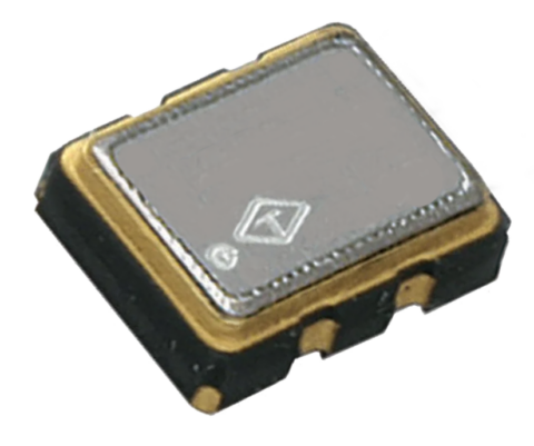
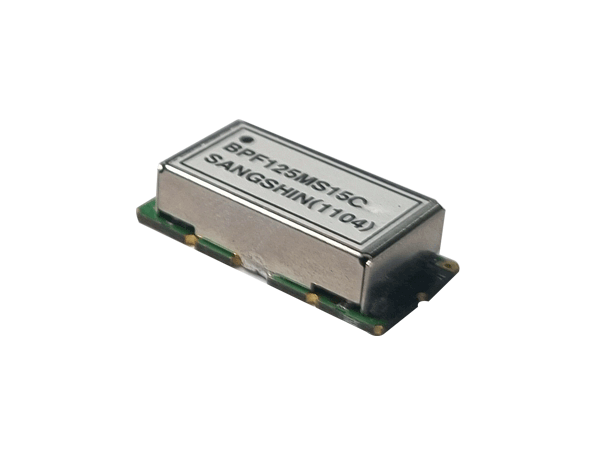
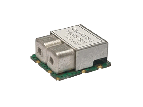
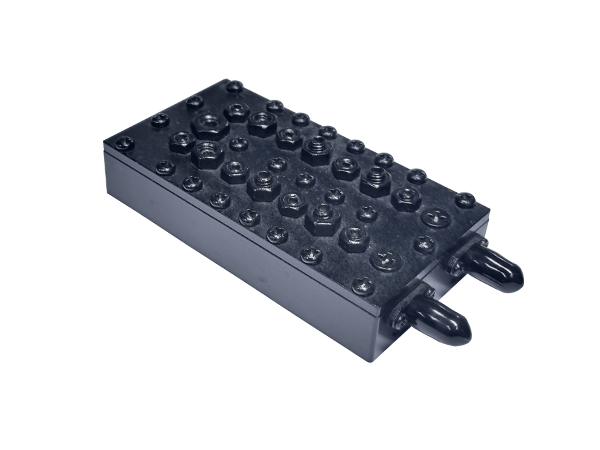
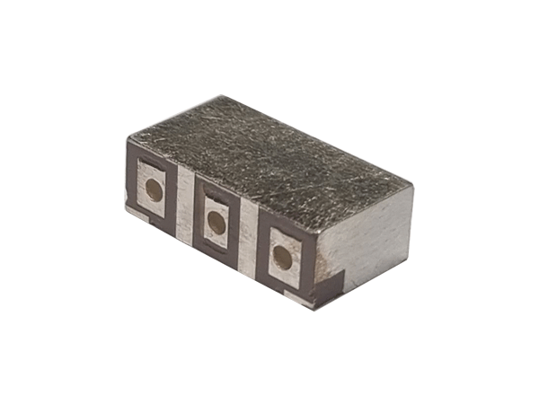
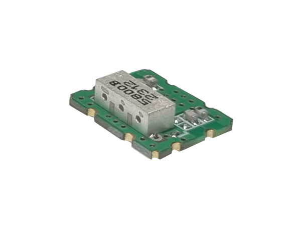
This range comprises 11 band-rejection and notch RF filter parts covering 18 technical frequency paths. Each filter is configured to attenuate a specified unwanted frequency or frequency band while retaining the required transmission paths outside the rejection region. Available implementations include LC, discrete, cavity and ceramic monoblock technologies. Both single-path and dual-path configurations are represented, allowing selection for different RF architectures and frequency plans. The listed path boundaries extend from 10 MHz to 6800 MHz, although the range does not provide continuous coverage across this entire span. Maximum insertion-loss ratings range from 1.5 dB to 5 dB, with minimum specified rejection levels from 10 dB to 60 dB. Typical applications can include mobile communications, GPS, WLAN, Wi-Fi, RFID and other radio systems requiring interference suppression or frequency isolation.
Range features
A high level overview of what this range offers
- 11 part-numbered options across 18 frequency paths – Provides a choice of frequency plans and rejection characteristics.
- LC, discrete, cavity and ceramic monoblock technologies – Supports selection according to frequency, package size and attenuation requirements.
- One-path and two-path configurations – Accommodates single transmission bands or pass regions on either side of a rejected band.
- Path boundaries from 10 MHz to 6800 MHz – Covers applications across several RF frequency ranges without implying continuous coverage.
- Maximum insertion loss from 1.5 dB to 5 dB – Allows passband loss to be considered during the RF link-budget calculation.
- Minimum attenuation from 10 dB to 60 dB – Supports different levels of unwanted-signal suppression.
- Minimum return loss from 5 dB to 15 dB – Provides defined impedance-matching criteria for integration.
- Package heights from 2.8 mm to 24 mm – Offers options for PCB-mounted and larger cavity-based assemblies.
- Specified rejection frequencies and bands – Helps engineers match each part to a known interferer or protected operating band.
What’s in this range?
All the variants in the range and a comparison of what they offer
| Part No. | Classification | Normalised Technology | Band | Frequency Paths | Start Freq. [MHz] | Center Freq. [MHz] | Stop Freq. [MHz] | Insertion Loss [dB/max.] | Return Loss [dB/min.] | Ripple [dB/max.] | Attenuation [dB/min.] | Dimensions (L × W × H) [mm] |
|---|---|---|---|---|---|---|---|---|---|---|---|---|
BEF465S30A | LC | LC | 1 | 450 | 465 | 480 | 2 | 15 | 1 | 25 @ 618.6 | 16.5 × 14.2 × 7 | |
BEF62R1962S240A | Discrete | Discrete | 1 | 1842.24 | 1962.24 | 2082.24 | 2 | 15 | 1 | 25 @ 1808.64 | 16.5 × 14.2 × 7 | |
BEF62R2140S240A | Discrete | Discrete | 1 | 2020 | 2140 | 2260 | 2 | 15 | 1 | 25 @ 2293.76 | 16.5 × 14.2 × 7 | |
BEF62R873S210A | Discrete | Discrete | 1 | 768 | 873 | 978 | 2 | 15 | 1 | 25 @ 1026.048 | 16.5 × 14.2 × 7 | |
BEF94MS28A | LC | LC | 2 | 10 | 40 | 70 | 4 | 14 | 3.5 | 20 @ 80 ~ 108 | 17 × 57 × 10 | |
BPF65R2450S100A | Discrete | Discrete | 2 | 1780 | 2077.5 | 2375 | 3 | 15 | 15 @ 2400 ~ 2500 | 16.5 × 32 × 7.2 | ||
CABRF20MR3450S100A | Cavity | Cavity | 2 | 300 | 1840 | 3380 | 5 | 5 | 60 @ 3400 ~ 3500 | 90 × 225 × 24 | ||
CABRF20MR3750S100A | Cavity | Cavity | 2 | 300 | 1990 | 3680 | 5 | 5 | 60 @ 3700 ~ 3800 | 90 × 225 × 24 | ||
MBEF33R1592S35B | Mono | Ceramic Monoblock | 2 | 790 | 875 | 960 | 1.5 | 8 | 1.5 | 25 @ 1575 ~ 1610 | 7.2 × 8.5 × 2.8 | |
MBEF33R5800SP150B | Mono | Ceramic Monoblock | 2 | 4880 | 5190 | 5500 | 1.5 | 12 | 1 | 10 @ 5725 ~ 5875 | 11.5 × 14.2 × 4 | |
MBEF43R1592S35A | Mono | Ceramic Monoblock | 2 | 700 | 1092.5 | 1485 | 1.5 | 10 | 1 | 20 @ 1575 ~ 1610 | 7 × 11.3 × 3.65 |
FAQs
for Band-Rejection Notch
A band-rejection or notch filter attenuates an unwanted frequency or defined frequency band while allowing frequencies outside the rejection region to pass. It can be used to suppress interference, isolate neighbouring services or protect sensitive receiver stages.
No. The lowest and highest listed frequency-path boundaries are 10 MHz and 6800 MHz respectively, but each part supports its own defined transmission paths and rejection frequency. Engineers should compare the individual start, centre and stop frequencies with the required frequency plan.
The range includes LC, discrete, cavity and ceramic monoblock implementations. The appropriate technology will depend on factors such as operating frequency, rejection requirement, allowable insertion loss, available space and mounting arrangement.
A two-path filter has two listed transmission regions, commonly positioned below and above the rejected frequency band. The start, centre and stop frequencies for both paths are shown separately in the specifications table.
Maximum insertion-loss ratings extend from 1.5 dB to 5 dB, depending on the part. This value should be included in the system link budget and checked against the conditions of the intended application.
CABRF20MR3450S100A and CABRF20MR3750S100A each specify at least 60 dB attenuation. Their rejection bands are 3400–3500 MHz and 3700–3800 MHz respectively.
MBEF33R5800SP150B specifies at least 10 dB attenuation from 5725 MHz to 5875 MHz. Its two listed transmission paths extend from 4880 MHz to 5500 MHz and from 6100 MHz to 6800 MHz.
MBEF33R1592S35B has the lowest listed height at 2.8 mm, with overall dimensions of 7.2 × 8.5 × 2.8 mm. Mechanical clearances, mounting details and PCB requirements should also be confirmed before selection.
Key parameters include the rejection frequency or band, transmission-path limits, insertion loss, return loss, ripple, minimum attenuation and package dimensions. The selected part should also be evaluated within the complete RF circuit to account for impedance matching, adjacent components and operating conditions.