H series RTD sensors
- Technology
- Platinum RTD sensors
- Partner
- YAGEO Nexensos GmbH
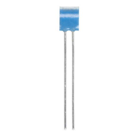
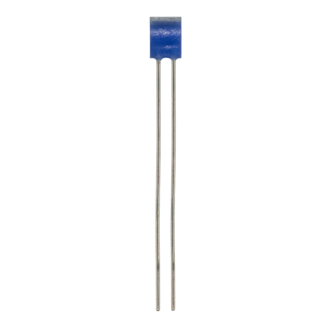
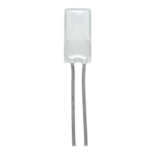
The YAGEO Nexensos H Series is a family of wired resistance temperature detectors (RTDs) designed for precise temperature measurement in applications where compact sensor dimensions and high operating temperatures are important. Available in multiple configurations, the range combines platinum sensing technology with small form factors to support integration into industrial equipment, thermal systems, and specialised measurement assemblies.
With model-dependent operating limits reaching up to 1,000°C, the H Series offers options for applications ranging from general high-temperature sensing to more demanding thermal environments. Pt100, Pt200, and Pt1000 resistance options, different temperature coefficients, and multiple connection and packaging configurations provide flexibility for application-specific sensor selection.
H Series RTDs provide temperature feedback for monitoring, control, and thermal characterisation. Their compact, wired construction supports integration into assemblies where space is limited and conventional temperature probes may be unsuitable.
Potential application areas include:
-Industrial process and equipment temperature monitoring -High-temperature machinery and thermal assemblies -Heating systems and thermal management equipment -Laboratory and test instrumentation -Specialised equipment requiring compact platinum sensing elements -Embedded temperature measurement in engineered assemblies
Application suitability depends on the selected model, mounting method, connection process, environmental conditions, and the manufacturer’s specified operating limits.
Range features
A high level overview of what this range offers
-
High-temperature measurement capability – Specified maximum temperatures range from 750°C to 1,000°C across the supplied configurations, supporting a variety of demanding thermal applications.
-
Compact sensor geometry– Sensor body lengths range from 2.3 mm to 3.9 mm, helping engineers integrate temperature sensing into space-constrained assemblies.
-
Platinum RTD technology – Platinum sensing provides a well-established basis for resistance-based temperature measurement and repeatable calibration when used with the appropriate measurement system.
-
Multiple nominal resistance options – Pt100, Pt200, and Pt1000 variants offer flexibility when matching sensor resistance to measurement electronics and circuit design.
-
Choice of temperature coefficients – The range includes 3850 ppm/K and 3770 ppm/K variants. Selecting the correct coefficient helps ensure compatibility with the required resistance-temperature relationship.
-
Wired construction for assembly integration – The wired format supports incorporation into customer-designed assemblies, with connection options varying by model.
-
Welding and brazing options – Specified models support welding, brazing, or both, giving manufacturers flexibility in mechanical and electrical integration.
-
Specified insulation resistance – The listed configurations specify insulation resistance of 100 MΩ or 500 MΩ. These values provide a useful selection parameter, subject to the applicable test conditions and datasheet requirements.
-
Low stated self-heating coefficients – Specified values range from 0.2 K/mW to 0.58 K/mW under the stated conditions. This characteristic helps engineers evaluate the potential influence of measurement current on the sensor’s indicated temperature.
-
Flexible packaging options – Plastic bags, blister reels, and slide blisters are available across the listed configurations, supporting different component handling and manufacturing requirements.
Downloads
for H series RTD sensors
What’s in this range?
All the variants in the range and a comparison of what they offer
Specifications
| Parameter | HD421 | HL220 | HDA420 | HDZ420 |
|---|---|---|---|---|
Construction | Wired | Wired | Wired | Wired |
Nominal resistance, R₀ | Pt100 (100 Ω) | Pt1000 (1,000 Ω) | Pt200 (200 Ω) | Pt200 (200 Ω) |
Temperature coefficient | 3850 ppm/K | 3850 ppm/K | 3770 ppm/K | 3850 ppm/K |
Tolerance class | F 0.6 (2B) | F 0.6 (2B) | See datasheet | See datasheet |
Length, L | 3.9 +0.5/−0.1 mm | 2.3 ±0.15 mm | 3.9 ±0.15 mm | 3.9 ±0.15 mm |
Width, W | 2.1 ±0.3 mm | 1.9 ±0.15 mm | 1.9 ±0.2 mm | 1.9 ±0.2 mm |
Height, H | 1.1 ±0.3 mm | 1.0 ±0.3 mm | 1.0 ±0.3 mm | 1.0 ±0.3 mm |
Lead length, LL | 6 ±1 mm | 8 ±1 mm | 3.7 ±0.5 mm | 3.7 ±0.5 mm |
Connection technology | Welding, brazing | Welding, brazing | Welding, brazing | Welding only |
Insulation resistance | 100 MΩ | 100 MΩ | 100 MΩ | 500 MΩ |
Self-heating coefficient | 0.2 K/mW at 0°C | 0.4 K/mW at 0°C | 0.2 K/mW at 0°C | 0.58 K/mW in room-temperature air at 3 m/s |
Packaging | Slide blister | Plastic bag | Plastic bag or blister reel | Blister reel |
Minimum temperature | −70°C | −70°C | −40°C | −40°C |
Maximum temperature | 850°C | 750°C | 900°C | 1,000°C |
FAQs
for H series RTD sensors
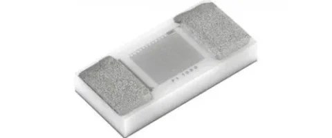
The sinterable SC version is intended for assemblies where the sensor is attached through a rear-side silver-sinter joint and connected from the top by ultrasonic thick-wire bonding. This differs from a conventional reflow-soldered 1206 RTD and is relevant when the sensing element must sit close to a heat-generating die or substrate. The AgPd rear metallisation supports the sintering process, while the AgPt top surface supports wire bonding. Select this version when the assembly line can control the sinter paste, pressure, temperature profile and bonding parameters; otherwise, a solderable SMD RTD may be easier to integrate.
Use 0.1 to 0.3 mA as the specified measuring-current range for the Pt1000 element, while checking the complete analogue front end at the highest expected resistance. At 0°C and 1000 Ω, these current limits dissipate approximately 0.01 to 0.09 mW; with unassembled self-heating below 0.4 K/mW, the corresponding temperature rise is below roughly 0.004 to 0.036 K. The mounted thermal path can change this behaviour, and constant-current excitation increases power as resistance rises. The upper current can improve signal level, but a lower current or pulsed measurement may be preferable where the thermal-error budget is tight.
Class F0.6 (2B) is declared for continuous operation from -50 to +200°C, so it remains the stated selection criterion across the full operating range. It should not be interpreted as a fixed ±0.6°C error at every temperature; resistance conversion and tolerance assessment must follow DIN EN IEC 60751. The sensor has a nominal resistance of 1000 Ω at 0°C and a temperature coefficient of 3850 ppm/K, which must be matched by the measurement electronics and linearisation method. The system uncertainty budget should also account for excitation accuracy, interconnection effects, ADC error, reference stability and the intended calibration strategy.
The maximum stated R₀ drift is 0.23% after each of three independently performed tests: 1000 hours at +200°C with at least 0.1 mA, 1000 hours at +85°C and 85% relative humidity, and 1000 cycles between -40 and +150°C. For a Pt1000 element, 0.23% corresponds to 2.3 Ω at 0°C, although this is a resistance-drift limit rather than a complete temperature-error statement. The tests address thermal endurance, damp heat and repeated temperature cycling. Designers should compare the limit with the application’s calibration interval, conversion algorithm and expected lifetime temperature profile.
Rear attachment uses the AgPd thick-film surface for silver sintering, while the AgPt top surface is intended for ultrasonic thick-wire bonding. The available process data specifies rear shear strength above 10 N/mm² minimum and above 20 N/mm² mean, together with a front pull value above 210 cN when using 300 µm Al H11 thick wire. These process-characterisation values do not replace qualification on the final substrate, sinter paste, bond wire and encapsulation stack. Production acceptance criteria should be established using representative assemblies, with checks that cleaning, pressure, thermal profiles and bond settings do not damage the RTD or compromise its thermal interface.
No, the stated 7.5 kV value should not be treated as a guaranteed isolation rating for the completed assembly. It is based on the theoretical material properties of the substrate and the specified sensor geometry. Assembly processing, encapsulant selection and the shape of the potting meniscus can reduce dielectric strength in the application. Engineers should validate creepage, clearance, partial-discharge behaviour and dielectric withstand at system level using the actual sensor placement, mounting materials and environmental conditions.
Order number 5164075 is supplied in wafer-frame packaging, while 5195006 is supplied in blister-reel packaging. The reel format is face-up, accommodates up to 4200 pieces and uses an 8 mm tape with a 3.55 × 1.95 × 0.8 mm cavity and 4 mm pitch. The sensor is classified as MSL 1 and has a minimum unopened storage period of nine months in its original packaging. Wafer-frame packaging can suit die-style handling and specialised process flows, whereas the blister reel may be more convenient for automated feeders; the final selection depends on the assembly equipment and traceability plan.
Yes, the construction is intended for installation on power-electronics assemblies close to a heat source or semiconductor die, using the rear sintered interface and top-side connections. Positioning the element near the thermal source can reduce thermal-path delay and spatial error, provided the mounting stack represents the temperature that the control system needs to measure. The top-mounted terminations support electrically isolated positioning, but dielectric performance must still be validated after installation and encapsulation. Keep the continuous -50 to +200°C tolerance-class range in view, and model local gradients, switching losses and encapsulation effects before fixing the final sensor location.