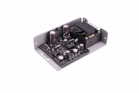
3600 W M-CRPS Titanium Power Supply
- Technology
- DC-DC uninterruptible power supplies
- Partner
- Advanced Energy
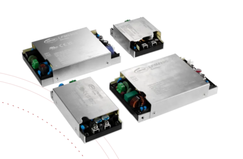
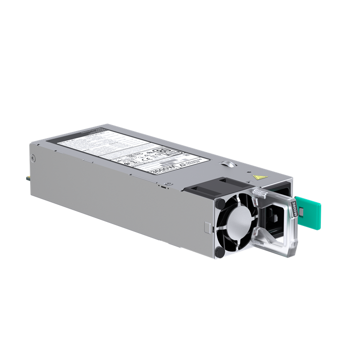
The CSU3600AT-9-3M0 is a 3600 W front-end AC-DC power supply for modular common redundant power supply architectures. It converts the available AC or specified DC input into a regulated 54 V bus for downstream DC-DC converters, alongside a separate 12 V standby output. The main rail delivers up to 66.7 A, making the unit suitable for servers, storage platforms and networking equipment with concentrated power requirements. Its 1U M-CRPS construction helps designers allocate more chassis space to processing, storage and communication hardware. N+N and N+1 redundancy, hot-plug operation and active current sharing support power shelves that must remain serviceable during operation. PMBus communication provides access to monitoring, reporting and control functions through the system management interface. Forward-airflow operation is rated for full output from –5 to 55 °C, subject to the stated input-power limits.
Range features
A high level overview of what this range offers
- 3600 W high-line rating with 54 V/66.7 A output: Supports distributed power architectures with high bus-power requirements.
- 12 V/3 A standby output: Supplies management and control circuits independently of the main rail.
- 96% peak efficiency and 80 PLUS Titanium rating: Limits conversion losses under the applicable operating conditions.
- Multiple AC input bands and documented 240 VDC operation: Accommodates different power-distribution arrangements.
- Active power factor correction: Provides a power factor above 0.92 from 10% load.
- 11 ms hold-up time at full load: Supports continuity during brief input disturbances.
- N+N and N+1 redundancy with hot-plug operation: Enables serviceable redundant power shelves.
- Active current sharing within ±2%: Helps parallel supplies divide the load from 25% of rated PSU load.
- PMBus, SMBAlert and selectable addressing: Supports system-level monitoring, reporting and control.
- 1U × 73.5 × 185 mm M-CRPS format: Reduces the space required for front-end power conversion.
- Field-upgradable firmware with firmware security: Simplifies maintenance while retaining controlled firmware handling.
- Forward-airflow operation from –5 to 55 °C at full power: Provides a defined thermal operating range for chassis design.
Downloads
for 3600 W M-CRPS Titanium Power Supply
What’s in this range?
All the variants in the range and a comparison of what they offer
Specifications
| Category | Parameter | Specification |
|---|---|---|
General | Part number | CSU3600AT-9-3M0 |
General | Product type | Front-end bulk AC-DC power supply |
General | Form factor | 1U M-CRPS |
General | Dimensions | 1U × 73.5 × 185 mm |
General | Power density | 110 W/in³ |
General | Target applications | Server, storage and networking equipment |
Input | Input range and available output power | 90–132 VAC: 1400 W |
Input | Documented DC input | 240 VDC |
Input | Frequency | 47–63 Hz |
Input | Maximum input current | 17.5 A; average limit of 18 A for North America and 17 A elsewhere |
Input | Cold-start inrush current | 55 A peak |
Input | Peak efficiency | 96.0%; 80 PLUS Titanium rating |
Input | Power factor | Greater than 0.92 from 10% load |
Input | Hold-up time | 11 ms at full load |
Input | Leakage current | Less than 0.585 mA |
Input | Conducted EMI | Class A |
Input | Radiated EMI | Class A |
Main output | Nominal voltage | 54 V, with –0.4%/+0.4% nominal-setting tolerance |
Main output | Output current | 1–66.7 A; the 1 A minimum applies to step-load conditions |
Main output | Total regulation | ±5% |
Main output | Dynamic-load regulation | ±8% |
Main output | Ripple | 1% maximum |
Main output | Current sharing | Within ±2% of full-load rating from 25% of rated PSU load |
Main output | Capacitive loading | 100–15,000 µF |
Main output | Rise time | 10–70 ms |
Standby output | Nominal voltage | 12.0 V, with –3.5%/+3.5% nominal-setting tolerance |
Standby output | Output current | 0.1–3 A |
Standby output | Total regulation | ±5% |
Standby output | Dynamic-load regulation | ±8% |
Standby output | Ripple | 1% maximum |
Standby output | Capacitive loading | 270–4,700 µF |
Standby output | Rise time | 10–70 ms |
Operation | Redundancy | N+N, N+1 and cold-redundancy operation |
Operation | Hot-plug capability | Yes |
Operation | Digital interface | PMBus compliant with I²C clock and data connections |
Operation | Additional control | Closed-loop throttle, remote sense, current-share and status signals |
Operation | Firmware | Field-upgradable firmware with firmware security |
Connection | Input connection | C20 |
Connection | Output connection | Card-edge connector aligned with the M-CRPS 54 V requirement |
Connection | Recommended mating connector | FCI Amphenol HPG12P14SRT153T or equivalent |
Environment | Operating temperature, forward airflow | –5 to 55 °C at full rated power; short-term operation up to 65 °C requires derating |
Environment | Operating altitude | Up to 10,000 feet; safety creepage and clearance rated for 5,000 m altitude for CQC |
Environment | Operating relative humidity | 5–95%, non-condensing |
Environment | Non-operating temperature | –40 to +70 °C |
Environment | Shipping and storage humidity | 5–95%, non-condensing |
Environment | Non-operating altitude | Up to 50,000 feet |
Reliability | MTBF | 500,000 hours at 55 °C, 100% load and nominal input |
Reliability | Operating life | Minimum five years at 55 °C, 85% load and nominal input |
Reliability | Warranty | Two years |
Compliance | Harmonic current | EN 61000-3-2 |
Compliance | Product standards and environmental status | IEC 62368 and RoHS |
Safety and market approvals | Listed marks and certificates | UL/cUL, CB Test Certificate, CE, KC, EAC, BIS, CQC and BSMI |
Output Connector Pin Configuration
| A-side contact | Signal | B-side contact | Signal |
|---|---|---|---|
A1–A9 | POWER GND | B1–B9 | POWER GND |
A10–A18 | +54V | B10–B18 | +54V |
A19 | SDA | B19 | A0 addressing |
A20 | SCL | B20 | A1 addressing |
A21 | PSON# | B21 | 12VSB |
A22 | SMBAlert# | B22 | CR_BUS |
A23 | RETURN_SENSE | B23 | ISHARE |
A24 | +54V_REMOTE_SENSE | B24 | Imon |
A25 | PWOK | B25 | VIN_GOOD |
Digital Interface Addressing
| A1 | A0 | PMBus address | IPMI FRU address |
|---|---|---|---|
0 | 0 | B0h | A0h |
0 | 1 | B2h | A2h |
1 | 0 | B4h | A4h |
1 | 1 | B6h | A6h |
FAQs
for 3600 W M-CRPS Titanium Power Supply
The available power must be matched to the operating input band rather than assumed to be 3600 W at every voltage. The stated ratings are 1400 W at 90–132 VAC, 3900 W at 180–219 VAC, 3200 W at 220–239 VAC and 3600 W at 240–264 VAC, while the documented DC input point is 240 VDC. This means a universal-input system requires a power budget that changes with regional mains conditions. Because the listed AC power steps are not monotonic, the exact operating point should be confirmed during design validation. Low-line operation in particular should not be sized against the 3600 W headline rating.
Yes, it is intended for N+N and N+1 redundant configurations and supports hot-plug operation, cold redundancy and active current sharing. The sharing accuracy is within ±2% of the full-load rating once each supply is operating from 25% of its rated load. This helps parallel modules divide the 54 V load predictably, but the shelf controller, backplane, sequencing and protection strategy still need to be engineered at system level. The main output also carries a 1 A minimum requirement for step-load conditions. Designs should therefore assess both steady-state sharing and transient behaviour when modules are inserted, removed or placed into standby.
Full rated power is specified from –5 to 55 °C with forward airflow. Short-term operation up to 65 °C is allowed only with derating, but the derating value is not defined, and reverse-airflow operation is also marked TBD. The 1U, 73.5 × 185 mm enclosure and 110 W/in³ power density make airflow impedance, inlet temperature and recirculation important parts of the chassis design. Thermal qualification should use the intended fan curve and rack pressure conditions rather than free-air assumptions. If reverse airflow or operation above 55 °C is required, obtain a confirmed derating profile before freezing the mechanical design.
PMBus communication is provided through SDA on A19 and SCL on A20, with SMBAlert# on A22 and the A0/A1 address-selection inputs on B19 and B20. The four PMBus addresses are B0h, B2h, B4h and B6h for address-bit combinations 00, 01, 10 and 11. The corresponding IPMI FRU addresses are A0h, A2h, A4h and A6h. These options allow several supplies to share a management bus without address collisions, provided the backplane sets A0 and A1 correctly. The control design should also account for PSON#, PWOK, VIN_GOOD, current-share and remote-sense signals available at the output connector.
The 54 V main output supports 1 to 66.7 A, while the 12 V standby rail supports 0.1 to 3 A. Allowed capacitive loading is 100 to 15,000 µF on the main rail and 270 to 4,700 µF on standby, with a stated rise-time range of 10 to 70 ms for both outputs. Main and standby total regulation is ±5%, dynamic regulation is ±8% and ripple is limited to 1%. These limits should be checked against downstream converter start-up current, bus capacitance and hold-up requirements. A system with large distributed capacitance may need staged enable or inrush management to remain within the permitted start-up envelope.
The power supply includes active power factor correction, with power factor above 0.92 from 10% load, and is listed for EN 61000-3-2 harmonic compliance. Conducted and radiated emissions are specified to Class A, while cold-start inrush is 55 A peak and leakage current is below 0.585 mA. Listed safety and market approvals include UL/cUL, CB, CE, KC, EAC, BIS, CQC and BSMI, alongside IEC 62368 and RoHS status. These entries support component selection, but they do not replace system-level EMC and safety testing. The final chassis, filtering, earthing, cabling and airflow arrangement can still affect compliance.
The stated MTBF is 500,000 hours at 55 °C, 100% load and nominal input, while operating life is a minimum of five years at 55 °C, 85% load and nominal input. These figures describe different reliability measures and should not be treated as interchangeable service-life guarantees. The two-year warranty, hot-plug capability and field-upgradable firmware support a maintainable redundant power architecture. In practice, service planning should consider inlet temperature, loading profile, fan duty, redundancy policy and the time required to update firmware safely. PMBus monitoring can also be incorporated into predictive-maintenance logic, provided the host system defines suitable alarm thresholds and response actions.