3200 W M-CRPS Titanium Power Supply
- Technology
- DC-DC uninterruptible power supplies
- Partner
- Advanced Energy
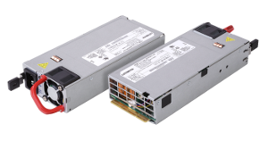
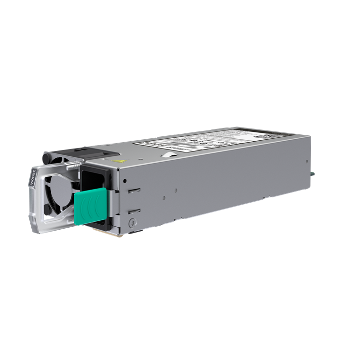
The CSU3200AT-3-6M0 is a front-end bulk power supply for modular hardware common redundant power supply applications. It converts 90 to 264 VAC or 192 to 310 VDC into a regulated 12.2 V main output for downstream DC-DC converters, together with a 12 V standby rail. The full 3200 W rating is available from 198 to 264 VAC and at 240 VDC, while lower AC input ranges provide reduced output power. Its 1U x 73.5 x 185 mm format is intended for compute, storage and networking equipment where chassis space is constrained. Hot-plug operation, active current sharing and N+1, N+N or cold-redundant configurations support serviceable power architectures. I²C and PMBus functions provide monitoring, reporting and control, with additional support for closed-loop throttling, field-upgradeable firmware and firmware security. Peak efficiency of 96%, active power factor correction and controlled inrush current help manage input power and thermal requirements.
Range features
A high level overview of what this range offers
- 3200 W high-line output: Supplies up to 262.3 A for high-current 12 V distributed power architectures.
- 96% peak efficiency and 80 PLUS Titanium rating: Limits conversion losses and can reduce associated cooling demand.
- AC and high-voltage DC input compatibility: Operates from 90 to 264 VAC or 192 to 310 VDC for different power infrastructures.
- Compact M-CRPS format: The 1U x 73.5 x 185 mm construction preserves chassis volume for processors, storage and networking hardware.
- Active current sharing: Maintains a sharing error of ±4% from 5% to 100% of rated current for balanced parallel operation.
- Flexible redundancy: Supports N+1, N+N and cold-redundant power-system configurations.
- Hot-pluggable construction: Allows a power module to be exchanged without dismantling the host system.
- PMBus and I²C management: Provides digital monitoring, reporting, addressing and control functions.
- 12 V standby output: Supplies up to 3 A for auxiliary and management circuitry when the main rail is inactive.
- Firmware lifecycle support: Includes field-upgradeable firmware and firmware security.
- Managed input behaviour: Active power factor correction and inrush control help limit upstream current demand.
- 11 ms full-load hold-up time: Supports continuity through short input interruptions under the specified operating condition.
- Class A emissions: Supports integration into commercial and industrial equipment subject to system-level EMC testing.
Downloads
for 3200 W M-CRPS Titanium Power Supply
What’s in this range?
All the variants in the range and a comparison of what they offer
Specifications
| Category | Specification | Value |
|---|---|---|
Identification | Part number | CSU3200AT-3-6M0 |
Power | Maximum output power | 3200 W |
Power | Output power by AC input | 1400 W at 90 to 132 VAC; 2900 W at 180 to 198 VAC; 3200 W at 198 to 264 VAC |
Power | Output power at DC input | 3200 W at 240 VDC |
Input | AC input range | 90 to 132 VAC and 180 to 264 VAC |
Input | DC input range | 192 to 310 VDC |
Input | Maximum input current | 16 A at 200 VAC |
Input | Frequency | 47 to 63 Hz |
Input | Peak efficiency | 96.0%; 80 PLUS Titanium rating |
Input | Power factor | Greater than 0.9 from 10% load; greater than 0.98 at 50% load |
Input | Inrush current | 35 A peak, cold start |
Input | Hold-up time | 11 ms at full load |
Input | Leakage current | Less than 0.583 mA |
Input | Conducted emissions | Class A |
Input | Radiated emissions | Class A |
Main output | Nominal voltage | 12.2 V, with −0.20% to +0.20% nominal setting tolerance |
Main output | Output current | 262.3 A maximum; 1.0 A minimum for transient testing; regulation maintained at zero load |
Main output | Total regulation | −5% to +5% |
Main output | Dynamic load regulation | −5% to +5% |
Main output | Ripple | 1% maximum |
Main output | Current-sharing error | ±4% of rated current from 5% to 100% load |
Main output | Capacitive loading | 3,300 to 70,000 µF; 2,000 µF of external capacitance required for cold redundancy |
Main output | Rise time | 10 to 70 ms |
Standby output | Nominal voltage | 12.0 V, with −3.5% to +3.5% nominal setting tolerance |
Standby output | Output current | 0.1 to 3.0 A |
Standby output | Total regulation | −5% to +5% |
Standby output | Dynamic load regulation | −5% to +5% |
Standby output | Ripple | 1% maximum |
Standby output | Capacitive loading | 270 to 4,700 µF |
Standby output | Rise time | 10 to 70 ms |
Mechanical | Form factor | 1U x 73.5 x 185 mm |
Mechanical | Airflow direction | Forward |
Redundancy | Supported modes | N+1, N+N and cold redundancy |
Redundancy | Parallel operation | Active current sharing and hot-plug operation |
Management | Digital interface | I²C and PMBus compliant |
Management | Functions | Monitoring, reporting, control and closed-loop throttling |
Firmware | Maintenance and security | Field-upgradeable firmware and firmware security |
Environment | Operating temperature | −5 to +55°C at full rated power |
Environment | Operating altitude | Up to 10,000 feet |
Environment | Operating relative humidity | 5% to 95%, non-condensing |
Environment | Non-operating temperature | −40 to +70°C |
Environment | Storage relative humidity | 5% to 95%, non-condensing |
Environment | Non-operating altitude | Up to 50,000 feet |
Environment | Shock and vibration | Operating and non-operating random shock and vibration |
Reliability | MTBF | Greater than 400,000 hours at 40°C |
Reliability | Operating life | Minimum five years at 55°C, 80% load and nominal input |
Compliance | Environmental | RoHS compliant |
Compliance | EMC and harmonics | Conducted and radiated EMI Class A; EN 61000-3-2 |
Safety | Standards and marks | IEC 62368, UL/cUL, CB Test Certificate, CE, KC, EAC, BIS, CQC and BSMI |
Connection | AC input connector | IEC 320-C20; recommended mating connector IEC 320-C19 |
Connection | Output connector | Card-edge; recommended mating connector 10147875-001LF |
Warranty | Warranty period | Two years |
Output connector pin configuration
| Connector position | Signal | Connector position | Signal |
|---|---|---|---|
A1–A9 (P1–P3) | POWER GND | B1–B9 (P7–P9) | POWER GND |
A10–A18 (P4–P6) | +12V | B10–B18 (P10–P12) | +12V |
A19 (S1) | SDA | B19 (S8) | A0, digital or analogue addressing |
A20 (S2) | SCL | B20 (S9) | A1 addressing/DSSI |
A21 (S3) | PSON# | B21 (S10) | 12VSB |
A22 (S4) | SMBAlert# | B22 (S11) | CR_BUS |
A23 (S5) | RETURN_SENSE/PS_KILL | B23 (S12) | ISHARE |
A24 (S6) | +12V REMOTE SENSE | B24 (S13) | IMON |
A25 (S7) | PWOK | B25 (S14) | VINOK |
Pin names show the regular connector position followed by the corresponding high-power connector position in parentheses. The +12 V remote-sense function is not enabled on the CSU3200AT-3-6M0.
Management-bus addressing
| Interface | A1 | A0 | Write address | Read address |
|---|---|---|---|---|
PMBus | 0 | 0 | B0h | B1h |
PMBus | 0 | 1 | B2h | B3h |
PMBus | 1 | 0 | B4h | B5h |
PMBus | 1 | 1 | B6h | B7h |
IPMI FRU | 0 | 0 | A0h | A1h |
IPMI FRU | 0 | 1 | A2h | A3h |
IPMI FRU | 1 | 0 | A4h | A5h |
IPMI FRU | 1 | 1 | A6h | A7h |
FAQs
for 3200 W M-CRPS Titanium Power Supply
The available power depends directly on the input range. The rating is 1400 W at 90 to 132 VAC, 2900 W at 180 to 198 VAC and 3200 W at 198 to 264 VAC; 3200 W is also specified at 240 VDC within the 192 to 310 VDC input range. System power budgets should therefore use the lowest input condition that can occur in service rather than assuming 3200 W at all times. For N+1 or N+N systems, apply the relevant input-dependent limit to every installed unit before calculating the redundancy margin. This avoids a design that meets load demand at high line but loses capacity during low-line operation or input transfer.
The power supply supports hot-plug operation, active current sharing, cold redundancy and both N+1 and N+N configurations. Current-sharing error is limited to ±4% of rated current between 5% and 100% load, helping parallel units divide the demand without excessive imbalance. Cold-redundant operation requires 2,000 µF of external capacitance, while the permitted main-output capacitive load is 3,300 to 70,000 µF. The host backplane should correctly route PSON#, PWOK, CR_BUS and ISHARE signals and manage insertion, removal and fault states. Because remote sense is disabled on this model, conductor and connector losses must also be controlled within the system voltage budget.
The PMBus interface can be assigned one of four address pairs through the A1 and A0 addressing inputs. The available PMBus write/read pairs are B0h/B1h, B2h/B3h, B4h/B5h and B6h/B7h, while the corresponding IPMI FRU pairs run from A0h/A1h to A6h/A7h. SDA, SCL and SMBAlert# provide the core digital-management connections, with IMON, VINOK and PWOK supporting additional host supervision. Each parallel unit should be given a unique address combination where it shares the same management bus. Address allocation should be completed before backplane routing so that firmware, inventory and live telemetry can be associated with the correct physical power-supply bay.
The main rail is set to 12.2 V and can deliver up to 262.3 A, with a nominal setting tolerance of −0.20% to +0.20%. The 12.0 V standby output provides up to 3.0 A for management and auxiliary circuits. Both outputs have a total and dynamic regulation range of −5% to +5%, a maximum ripple value of 1% and a rise time between 10 and 70 ms. Downstream DC-DC converters should therefore be selected for the complete static and transient voltage window rather than only the nominal value. Remote sense is not active, so PCB copper, busbars and connector resistance must be designed to prevent excessive voltage drop at the load.
Full rated power is specified from −5 to +55°C with forward airflow through the power supply. The operating environment may have 5% to 95% relative humidity without condensation and an altitude of up to 10,000 feet. Non-operating limits extend from −40 to +70°C and up to 50,000 feet, which is relevant to transport and storage planning. Reliability figures include an MTBF above 400,000 hours at 40°C and a minimum operating life of five years at 55°C, 80% load and nominal input. Chassis airflow should be validated at the power-supply inlet because restricted exhaust paths or recirculated air can raise the actual operating temperature.
Maximum input current is 16 A at 200 VAC, while cold-start inrush can reach 35 A peak. Power factor is greater than 0.9 from 10% load and greater than 0.98 at 50% load, with peak conversion efficiency reaching 96%. The AC connection uses an IEC 320-C20 inlet with an IEC 320-C19 mating connector. Branch protection, cabling, rack power distribution, UPS capacity and generator capacity should account for both continuous current and simultaneous inrush from multiple units. The 11 ms hold-up time can bridge short input disturbances at full load, but transfer performance still needs to be verified with the selected upstream power equipment.
The module uses a 1U x 73.5 x 185 mm M-CRPS format with forward airflow and hot-plug construction. AC power enters through an IEC 320-C20 connector, while the DC and control interface uses a card-edge connection with mating part number 10147875-001LF. Dedicated contact groups carry POWER GND and +12 V, allowing the high output current to be divided across multiple terminals. Separate pins provide PMBus communications, addressing, standby power, current sharing, power-good and input-status functions. The backplane, extraction path, airflow seals and connector engagement should all be checked together before the chassis design is released for tooling.
The unit carries an 80 PLUS Titanium efficiency rating and identifies RoHS, EN 61000-3-2, IEC 62368 and Class A conducted and radiated emissions compliance. Safety and market-access marks include UL/cUL, CB, CE, KC, EAC, BIS, CQC and BSMI. Class A emissions should be treated as an equipment-level condition rather than a guarantee that the finished host system will pass without additional filtering or shielding. Operating altitude is specified to 10,000 feet, while safety creepage and clearance are rated to 5,000 metres for CQC requirements. Final certification planning should match the destination market, enclosure, grounding, cabling and complete system configuration.