Defiant Future™ DF150 power supply
- Technology
- AC-DC uninterruptible power supplies
- Partner
- Advanced Energy
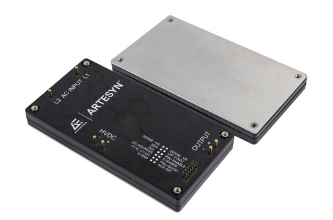
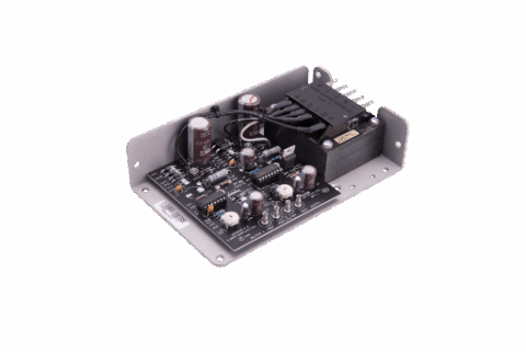
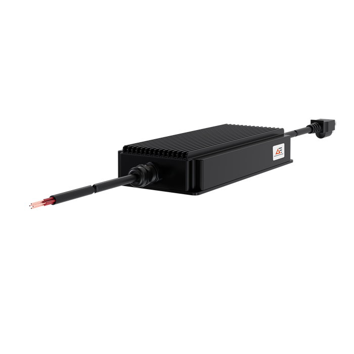
The DF150-27-BH3 is a fully enclosed, single-output AC-DC power supply from the Defiant Future™ DF150 series. It converts nominal 115 or 230 VAC input power into a regulated 27 VDC output rated for loads up to 5.93 A and 160 W. The BH3 configuration combines a black enclosure, a mounted heatsink for convection cooling and a 4 ft AC input cable fitted with a NEMA 5-15P plug. It is intended for defence, industrial, telecommunications, transport and energy equipment exposed to temperature extremes, moisture, altitude, shock, vibration or electromagnetic interference. The supply has defined MIL-STD-461G and MIL-STD-810H test coverage together with IP67 protection for temporary water immersion. Fanless operation eliminates an internal cooling fan, while the wider DF150 series offers convection- and baseplate-cooled configurations. As a standard product, the DF150 can support shorter deployment and production-scaling programmes than a fully bespoke power design, subject to application qualification and availability.
Range features
A high level overview of what this range offers
- 160 W single output at 27 VDC and 5.93 A: Supplies regulated power for 27 V defence and industrial loads.
- 90 to 132 VAC and 180 to 264 VAC input ranges: Supports nominal 115 and 230 VAC power systems.
- Fanless convection or conduction cooling: Removes fan noise, airflow dependency and fan maintenance requirements.
- −46°C to +60°C operating range: Accommodates equipment used in cold and high-temperature environments.
- MIL-STD-810H environmental test coverage: Addresses temperature, humidity, altitude, vibration and shock conditions.
- MIL-STD-461G EMI/EMC test coverage: Provides defined conducted and radiated emissions and susceptibility performance.
- IP67 ingress protection: Supports temporary immersion in water to 1 metre for 30 minutes.
- Overcurrent, overvoltage and overtemperature protection: Provides controlled responses to electrical and thermal fault conditions.
- Less than 1 mArms leakage current: Supports systems with defined earth-leakage requirements.
- Partial silicone potting and enclosed construction: Supports applications where moisture, dust and mechanical stress must be considered.
Downloads
for Defiant Future™ DF150 power supply
What’s in this range?
All the variants in the range and a comparison of what they offer
Specifications
| Category | Specification | Value |
|---|---|---|
General | Series | Defiant Future™ DF150 |
General | Associated part number | DF150-27-BH3 |
General | Conversion type | AC-DC, single output |
Input | Input voltage range | 90 to 132 VAC / 180 to 264 VAC; nominal 115/230 VAC |
Input | Frequency | 47 to 63 Hz; nominal 50/60 Hz |
Input | Input fusing | Internal fuse on both line and neutral |
Input | Inrush current | Less than 50 Apk at 264 VAC, 25°C ambient, cold start, excluding X capacitors |
Input | Power factor | 0.98 at 90/115 VAC; 0.87 at 230 VAC; 100% load |
Input | Input current | Less than 2.2 Arms at 90 VAC, 50/60 Hz |
Input | Hold-up time | 16 ms minimum at 100% load |
Input | Efficiency | 90% minimum at 100% load and 25°C ambient |
Input | Leakage current | Less than 1 mArms under IEC 62368-1 conditions at 264 VAC, 50/60 Hz |
Isolation | Input to output | 3,000 VAC |
Isolation | Input to ground | 1,500 VAC |
Isolation | Output to ground | 500 VDC |
Output | Output setpoint | 27.0 VDC |
Output | Output current range | 0 to 5.93 A |
Output | Maximum power | 160 W |
Output | Total regulation | ±2.0%, combined line, load and temperature |
Output | Ripple and noise | 1.0% maximum Vp-p with 2 × 820 µF/35 V external capacitors |
Output | Low-temperature ripple | Below −10°C: ≤1.5% typical; ≤3.0% with additional external capacitance of 22,000 µF by −46°C |
Dynamic response | Load transient | ±5% of output voltage; recovery below 500 ms for a 50% load step at 1 A/µs |
Dynamic response | Overshoot and undershoot | Less than 3% under worst-case conditions |
Protection | Overcurrent protection | Trip at no more than 130% of full-load current; automatic recovery after fault removal |
Protection | Overvoltage protection | Trip at 110% to 135% of output voltage; latched shutdown requiring an input power cycle |
Protection | Overtemperature protection | Trip threshold TBA; automatic shutdown and recovery when temperature returns to a safe range |
Start-up | Turn-on delay | No more than 1.5 seconds |
Start-up | Rise time | Less than 0.5 seconds at high line; less than 1 second at low line |
Thermal | Cooling options | Conduction through a baseplate or convection through a mounted heatsink |
Environmental | Operating temperature | −46°C to +60°C |
Environmental | Storage temperature | −46°C to +85°C induced condition |
Environmental | Ingress protection | IP67; water immersion to 1 metre for 30 minutes |
Reliability | MTBF | More than 100,000 hours |
Mechanical | Conduction-cooled dimensions | 8.75 × 4.0 × 1.3 in |
Mechanical | Convection-cooled dimensions | 8.75 × 4.0 × 1.6 in |
Mechanical | Listed weight | 1.8 kg |
Mechanical | DC output | Bare wires with half-stripped leads |
Mechanical | Potting | Partial silicone potting |
EMI | Class B emissions | FCC Part 15 Class B and EN 55032 Class B |
Immunity | Immunity standard | EN 61000 |
Safety | Safety design target | UL, CSA, EN and IEC 62368-1 |
Compliance | Environmental | MIL-STD-810H test methods |
Compliance | EMI/EMC | MIL-STD-461G requirements |
Marking | European marking | CE for LVD, EMC and RoHS |
Warranty | Warranty period | 2 years |
MIL-STD-461G test coverage
| Requirement | Frequency range or test level |
|---|---|
CE102 – Conducted emission at 115 and 220 VAC | 10 kHz to 10 MHz |
RE102 – Radiated emission, Army ground | 2 MHz to 18 GHz |
RS103 – Radiated susceptibility, Army ground | 2 MHz to 30 MHz; 30 MHz to 1 GHz; 1 GHz to 18 GHz |
CS101 – Conducted susceptibility | 30 Hz to 150 kHz |
CS114 – Bulk cable injection | 10 kHz to 200 kHz |
CS115 – Impulse excitation | 30 Hz rate for one minute |
CS116 – Damped sinusoidal transients | 10 kHz to 100 MHz |
CS118 – Electrostatic discharge | Level 3 air/contact discharge, ±8 kV |
MIL-STD-810H environmental test coverage
| Test | Condition |
|---|---|
Operating temperature | −46°C to +60°C |
Storage temperature | −46°C to +85°C induced condition |
High-temperature operation | Method 501.7 Procedure II, Hot Dry A1, 60°C maximum |
High-temperature storage | Method 501.7 Procedure I, Hot Dry A1, 85°C maximum |
Low-temperature operation | Method 502.7 Procedure II, Cold C2, −46°C minimum |
Low-temperature storage | Method 502.7 Procedure I, Cold C2, −46°C minimum |
Humidity | Method 507.6 Procedure II, aggravated cycle, 10 cycles |
Altitude | Method 500.6 Procedure II, operation/air carriage, −1,500 to 50,000 ft |
Transport vibration | Method 514.8 Procedure I, Categories 4, 7, 8, 9 and 10 |
Installed vibration | Method 514.8 Procedure I, Categories 12, 13, 20 and 23 |
Shock | Method 516.8 Procedure I, functional shock, 40 G peak objective |
Ingress protection | IP67 immersion to 1 metre for 30 minutes |
Performance | Output ripple and noise maintained within specification; MTBF above 100,000 hours |
Ordering information
| Order-code segment | Available code or value | Meaning |
|---|---|---|
Model | DF150 | DF150 power-supply series |
Output voltage | 27 | 27 VDC output |
Colour | G / K / B | Green / khaki / black |
Cooling type | B / H | Conduction cooling through baseplate / convection cooling with mounted heatsink |
AC input cable | 1 / 2 / 3 | 4 ft cable with tin leads / 2 ft cable with NEMA 5-15P / 4 ft cable with NEMA 5-15P |
DC output cable | Blank | 2 ft cable with tin leads |
Order-code example: DF150-27-KB3 specifies a khaki enclosure, conduction cooling and a 4 ft AC cable with a NEMA 5-15P plug.
Associated configuration: DF150-27-BH3 specifies a black enclosure, convection cooling with a mounted heatsink and a 4 ft AC cable with a NEMA 5-15P plug. The blank DC cable segment denotes the standard 2 ft output cable with tin leads.
FAQs
for Defiant Future™ DF150 power supply
Yes, provided the AC supply remains within either 90 to 132 VAC or 180 to 264 VAC at 47 to 63 Hz. These ranges cover nominal 115 and 230 VAC systems, but the interval between 132 and 180 VAC is not defined as a valid operating region. At 90 VAC and 50/60 Hz, input current is below 2.2 Arms, while cold-start inrush is below 50 Apk at 264 VAC and 25°C, excluding X capacitors. Internal fuses are fitted to both the line and neutral conductors. Upstream protection, relays, connectors and switches should therefore be selected for the specified inrush and low-line current rather than only the 160 W output rating.
The DF150-27-BH3 is the black, convection-cooled configuration with a mounted heatsink and a 4 ft NEMA 5-15P AC input cable. It operates without a fan and is rated for ambient temperatures from −46°C to +60°C. The convection-cooled enclosure measures 8.75 × 4.0 × 1.6 inches and has a listed weight of 1.8 kg. Natural convection still depends on suitable installation clearances and ambient air movement, while no minimum airflow or derating curve is specified. Thermal performance should therefore be validated at the intended input voltage, load, mounting arrangement and maximum local temperature before the design is released.
A 1.0% maximum peak-to-peak ripple and noise limit is achieved with two external 820 µF, 35 V capacitors. Below −10°C ambient, ripple is stated as no more than 1.5% typical, while additional external capacitance of 22,000 µF is identified for a limit of no more than 3.0% by −46°C. Low-temperature capacitor ESR can increase sharply, so nominal capacitance alone is not sufficient for component selection. Ripple-current rating, temperature rating, ESR and the electrical characteristics of the output harness must also be considered. Engineers should validate ripple and transient response with the actual load, cable length and capacitor arrangement used in the final equipment.
Overcurrent protection trips at no more than 130% of the 5.93 A full-load rating, corresponding to no more than approximately 7.71 A, and recovers automatically after the fault is removed. Overvoltage protection operates between 110% and 135% of the 27 V output, equivalent to approximately 29.7 to 36.45 V. An overvoltage event latches the supply off and requires the AC input to be recycled before operation resumes. Overtemperature protection shuts the supply down and recovers automatically after it cools, but its trip temperature remains TBA. System protection should not rely solely on an unspecified thermal threshold where the load or surrounding equipment has a lower temperature limit.
The DF150 series covers environmental and electromagnetic conditions associated with rugged platforms, although final suitability depends on matching the test profile to the intended installation. MIL-STD-810H coverage includes operation from −46°C to +60°C, induced storage to +85°C, altitude from −1,500 to 50,000 ft, ten-cycle aggravated humidity, multiple vibration categories and a 40 G functional-shock objective. MIL-STD-461G coverage includes conducted and radiated emissions, conducted and radiated susceptibility, cable injection, impulse, damped-sinusoidal transient and ±8 kV ESD testing. These tests do not automatically qualify every final enclosure, cable arrangement or host platform. Engineers should compare the named methods, procedures and categories with the programme compliance matrix before selection.
The IP67 rating covers dust ingress and temporary immersion in water to a depth of 1 metre for up to 30 minutes. The first digit indicates dust-tight protection, while the second defines the stated temporary immersion condition. It does not establish suitability for indefinite submersion, high-pressure washing, salt fog, fuels or chemical exposure unless those conditions are qualified separately. Cable ends, joints and external connections can also create system-level ingress paths even when the power-supply enclosure is protected. Outdoor or wet-environment installations should therefore include suitable junction sealing, strain relief, drainage and verification of the complete assembled system.
The DF150 provides a minimum hold-up time of 16 ms at full load, which can bridge short input disturbances but may not cover longer transfer intervals. For a 50% load step with a 1 A/µs slew rate, output deviation is specified within ±5% of 27 V, with recovery in less than 500 ms. Worst-case overshoot and undershoot remain below 3%. Turn-on delay is no more than 1.5 seconds, while rise time is below 0.5 seconds at high line and below 1 second at low line. Designs with processors, radios or sensitive analogue loads should confirm that these start-up and transient characteristics remain within their undervoltage, reset and sequencing limits.
The isolation ratings are 3,000 VAC from input to output, 1,500 VAC from input to ground and 500 VDC from output to ground. Leakage current is below 1 mArms under IEC 62368-1 conditions at 264 VAC and 50/60 Hz. The safety design targets UL, CSA, EN and IEC 62368-1, together with CE marking for the Low Voltage, EMC and RoHS requirements. These figures provide a basis for insulation coordination and protective-earth planning within the host equipment. They do not replace system-level assessment of earthing, cable routing, creepage, clearance, accessible parts and protection against single-fault conditions.