PM800 – 800W Open Frame Medical Power Supply
- Technology
- Open / u-frame power supplies
- Partner
- FSP Protek
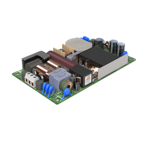
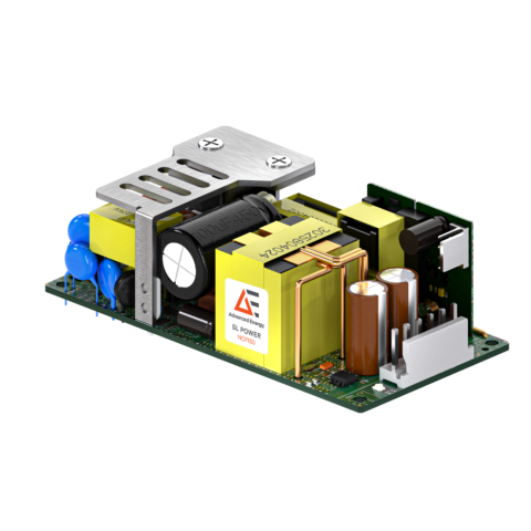
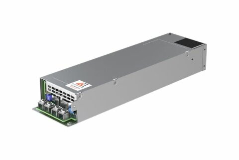
The PM800 is an 800 W AC-DC switching power supply designed for integration into medical and ITE equipment. It delivers 800 W continuously, with 1000 W peak capability for short-duration loads under the specified operating conditions. Seven fixed-output models cover voltages from 12 V to 54 V, allowing engineers to select the required voltage and current combination. The open-frame assembly incorporates a supporting chassis that also assists with heat dissipation and measures approximately 127 × 209.6 × 40.6 mm. BF class insulation, touch current up to 100 µA and earth leakage current up to 500 µA support applications with defined patient-protection requirements, subject to final equipment assessment. PFD, PS ON and remote-sense functions provide control and monitoring interfaces for system integration. Optional PMBus and current-sharing configurations are available where digital monitoring or parallel operation is required.
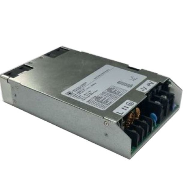
The PM800 is an open-frame AC-DC power supply for medical and ITE designs that need high continuous output power in a compact chassis-assisted format. It provides seven fixed-output options from 12 V to 54 V, plus integration features such as remote sense, PFD, PS ON and a 5 V standby rail. Optional PMBus communication and current-sharing capability extend the platform for monitored, redundant or parallel power architectures.
Range features
A high level overview of what this range offers
- 800 W continuous output – Supports sustained high-power loads within the stated thermal and input conditions.
- 1000 W peak capability – Accommodates short load peaks for less than 10 seconds at a 10% duty cycle and below 800 W average power.
- 12 V to 54 V output selection – Provides seven voltage and current combinations for different system architectures.
- 80–264 VAC input range – Supports equipment intended for operation across multiple mains regions.
- BF class insulation – Can support medical equipment requiring defined patient-protection insulation.
- Low leakage and touch current – Provides maximum values of 500 µA earth leakage and 100 µA touch current at 264 VAC and 63 Hz.
- Up to 94% typical efficiency – Helps limit conversion losses, depending on the selected model and input voltage.
- 0.98 typical power factor – Supports controlled input-current characteristics.
- Operation up to 5,000 metres – Enables use in equipment intended for higher-altitude locations.
- Remote-sense compensation – Compensates for cable voltage losses of up to 0.5 V.
- PFD and PS ON signals – Supports input-loss monitoring and TTL-level output control.
- 5 V standby output – Supplies auxiliary circuits with up to 2 A available.
- Less than 1 W standby consumption – Applies with the standby output operating at 5 V and 100 mA.
- Optional PMBus interface – Enables digital configuration, monitoring and fault reporting.
- Optional current sharing with OR-ing FET – Supports parallel and redundant power arrangements where correctly configured.
- Latched short-circuit protection – Protects the output during persistent short-circuit conditions.
- Class B conducted and radiated emissions – Addresses EN55011 and EN55032 Class B emission requirements.
Downloads
for PM800 - 800W Open Frame Medical Power Supply
What’s in this range?
All the variants in the range and a comparison of what they offer
| Specification | PM800-12C | PM800-13C | PM800-14C | PM800-16C | PM800-17C | PM800-18C | PM800-19C |
|---|---|---|---|---|---|---|---|
Nominal output | 12 V | 15 V | 24 V | 30 V | 36 V | 48 V | 54 V |
Minimum load | 0 A | 0 A | 0 A | 0 A | 0 A | 0 A | 0 A |
Maximum current | 66.67 A | 53.34 A | 33.34 A | 26.67 A | 22.23 A | 16.67 A | 14.82 A |
Peak current | 83.34 A | 66.67 A | 41.67 A | 33.34 A | 27.78 A | 20.84 A | 18.52 A |
Output tolerance | ±2% | ±2% | ±2% | ±2% | ±2% | ±2% | ±2% |
Ripple and noise | 120 mV | 150 mV | 240 mV | 300 mV | 360 mV | 480 mV | 480 mV |
Continuous/peak power | 800/1000 W | 800/1000 W | 800/1000 W | 800/1000 W | 800/1000 W | 800/1000 W | 800/1000 W |
Typical efficiency at 115/230 VAC | 90/92% | 90/92% | 91/93% | 91/93% | 92/94% | 92/94% | 92/94% |
| Specification | Value |
|---|---|
Power supply technology | AC-DC switching power supply |
Continuous output power | 800 W |
Peak output power | 1000 W under the specified peak-load conditions |
Input voltage | 80–264 VAC |
Input derating | 100% at 90 VAC, 90% at 85 VAC and 80% at 80 VAC |
Input frequency | 47–63 Hz; 400 Hz at 115 VAC |
Input current | 7.8 A RMS at 115 VAC; 4.1 A RMS at 230 VAC |
Power factor | 0.98 typical |
Earth leakage current | 500 µA maximum at 264 VAC and 63 Hz |
Touch current | 100 µA maximum at 264 VAC and 63 Hz |
Minimum efficiency | 90% on all models |
Switching frequency | 50 kHz typical |
Auxiliary standby output | 5 V, 2 A maximum |
Standby consumption | Less than 1 W at a 5 V/100 mA standby load |
Ripple and noise | 1% peak-to-peak maximum |
Remote-sense compensation | Up to 0.5 V cable-loss compensation |
Line regulation | ±0.5% maximum at full load |
Temperature coefficient | ±0.04%/°C maximum for all outputs |
Transient response | Maximum 4% excursion, recovering to within 1% of the final value within 500 µs after a 25% step-load change |
Overvoltage protection | 112–140% of nominal output voltage |
Overcurrent protection | Output protected under short-circuit conditions; latched operation stated |
Turn-on delay | 3 seconds maximum at 100 VAC |
Hold-up time | 20 ms minimum at 110 VAC |
Inrush current | 25 A at 115 VAC or 50 A at 230 VAC, at 25°C cold start |
Input-to-output withstand voltage | 4000 VAC, 2 MOPP |
Input-to-ground withstand voltage | 1500 VAC, 1 MOPP |
Output-to-ground withstand voltage | 1500 VAC |
MTBF | 100,000 hours at full load and 25°C ambient, calculated to MIL-HDBK-217F |
Operating temperature | −20°C to +70°C |
Storage temperature | −40°C to +85°C |
Relative humidity | 5–95%, non-condensing |
Temperature derating | 100% at +50°C, reducing linearly to 50% at +70°C |
Maximum operating altitude | 5,000 m |
Dimensions | 5 × 8.25 × 1.6 in; approximately 127 × 209.6 × 40.6 mm |
Approximate weight | 1.5 kg |
Fixing-screw penetration | 4 mm maximum from the outer chassis surface |
Insulation classification | BF class |
Markings shown | CE and RoHS |
Safety approval status | UL/CSA/TÜV 60601-1 and UL/CSA 62368-1 were identified as certification applications planned for Q1 2026; completion is not confirmed |
| Standard or Test | Performance |
|---|---|
EN55011/EN55032 | Class B conducted and Class B radiated emissions |
EN61000-3-2 | Harmonic distortion, Classes A and D |
EN61000-3-3 | Line flicker |
EN60601-1-2 and EN55035 | Listed EMC immunity standards |
EN61000-4-2 | ±15 kV air and ±8 kV contact ESD |
EN61000-4-3 | 9–28 V/m radiated immunity |
EN61000-4-4 | ±2 kV fast transient/burst |
EN61000-4-5 | ±1 kV differential and ±2 kV common-mode surge |
EN61000-4-6 | 10 Vrms conducted immunity |
EN61000-4-8 | 30 A/m magnetic-field immunity |
EN61000-4-11 | 30% voltage reduction for 500 ms and 100% reduction for 10 ms |
| Interface | Function |
|---|---|
PFD | TTL high during normal operation and TTL low after loss of input power; changes at least 1 ms before V1 falls 5% below nominal |
PFD recovery delay | Minimum 100 ms after V1 returns within regulation |
PS ON | TTL low turns on the output |
Remote sense | Compensates for up to 0.5 V of distribution loss |
SCL and SDA | Optional PMBus communication signals |
Current_Share_V | Optional current-sharing interface |
PDB_FAIL, A0, A1, PS_ALERT and PSKILL | Signals provided for redundancy and addressing functions |
| Suffix appended to the model number | Function |
|---|---|
-P | PMBus interface |
-C | Current-sharing function |
-CP | PMBus interface and current sharing |
| Connector | Pin | Function |
|---|---|---|
P1 | 1 | Live |
P1 | 2 | Neutral |
P1 | 3 | Ground |
P2 | 1 | V1 return |
P2 | 2 | +V1 |
P3 | 1 | +5 V standby |
P3 | 2 | +5 V standby |
P3 | 3 | Common return |
P3 | 4 | Common return |
P3 | 5 | SCL |
P3 | 6 | SDA |
P3 | 7 | Common return |
P3 | 8 | +5 V standby |
P3 | 9 | PFD |
P3 | 10 | PS ON |
P3 | 11 | Current_Share_V |
P3 | 12 | PDB_FAIL |
P3 | 13 | +V1 sense |
P3 | 14 | −V1 sense |
P3 | 15 | A0 |
P3 | 16 | A1 |
P3 | 17 | PS_ALERT |
P3 | 18 | PSKILL |
| Connector | Type |
|---|---|
AC input P1 | Dinkle DT-65-C01W-3 terminal with nickel-plated M4 screws |
DC output P2 | Dinkle 0166-8002C with nickel-plated M5 screw |
Signal and auxiliary output P3 | Molex 51110-1851 with locking ramp |
FAQs
for PM800 – 800W Open Frame Medical Power Supply
The series offers fixed outputs of 12 V, 15 V, 24 V, 30 V, 36 V, 48 V and 54 V. Maximum continuous current ranges from 66.67 A on the 12 V model to 14.82 A on the 54 V model.
The 1000 W rating is a short-duration peak value. Peak operation is limited to less than 10 seconds at a 10% duty cycle, while average output power must remain below 800 W.
Input derating applies below 90 VAC. Available output is rated at 100% at 90 VAC, 90% at 85 VAC and 80% at 80 VAC.
Full rated output is available up to an ambient temperature of +50°C under the stated operating conditions. Output must then be reduced linearly to 50% at +70°C, and the end-equipment design must provide suitable airflow and heat management.
A fixed airflow requirement is not stated. The thermal information covers both convection and forced-air cooling conditions, so the required cooling method should be established through testing in the final enclosure while observing the temperature-derating curve.
Remote sensing compensates for voltage loss in power cables or distribution conductors. The permitted compensation is up to 0.5 V, helping maintain the required voltage at the load when properly wired.
The standard interfaces include PFD for input-loss indication and PS ON for TTL-controlled output activation. Optional configurations can add PMBus communication, current sharing and redundancy-related signals.
Append -P for PMBus, -C for current sharing or -CP for both functions. For example, a PM800-14C model with both options becomes PM800-14C-CP.
BF insulation, leakage-current ratings and 2 MOPP input-to-output withstand voltage are defined. UL/CSA/TÜV 60601-1 and UL/CSA 62368-1 were marked as certification applications planned for Q1 2026, but completion is not confirmed, so current approval evidence should be verified before design-in.