Laser diode bars & arrays
- Technology
- DPSS lasers
- Partner
- Cutting Edge Optronics (CEO)
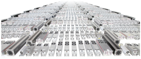
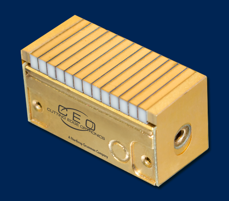
The 780–980 nm CW/QCW laser diode bars and arrays comprise a configurable product range rather than a single fixed part number. It includes conductively cooled, filtered-water-cooled and microchannel-cooled formats for integration into OEM laser systems and laboratory equipment. Standard wavelengths span 780 to 980 nm, including commonly used 808, 885 and 940 nm options, while custom wavelengths can be configured for specific applications.
Depending on the package and operating mode, the range extends from single-bar CW devices to multi-bar QCW arrays with kilowatt-level peak output. Applications include DPSS side and end pumping, materials processing, laser cutting, plastic welding, hair removal, LIDAR, LIBS, rangefinding, semiconductor manufacturing and high-energy laser systems. Engineers can select from A, G, H, Derringer, High Density Stack, Shooter, Microchannel Cooled Stack and array-submodule constructions according to the required thermal, optical, electrical and mechanical interface.
Range features
A high level overview of what this range offers
- CW and QCW operating formats – Accommodate continuous-output and pulsed laser architectures.
- 780–980 nm standard wavelength range – Covers established pump bands including 808, 885 and 940 nm.
- Conductive and liquid-cooling options – Allow the thermal interface to match available system infrastructure.
- Filtered non-DI water packages – Reduce the need for a dedicated deionised-water circuit in selected arrays.
- DI-water microchannel cooling – Supports dense stacks with up to 60 bars and high average power.
- Hard-soldered, expansion-matched constructions – Support mechanical stability under repeated thermal loading.
- Fast-axis and slow-axis lensing options – Help engineers adapt beam divergence to downstream optics.
- Multi-wavelength configurations – Can support systems requiring more than one emission wavelength.
- Bar pitches from 150 µm to 1.7 mm – Provide flexibility when balancing package density and thermal requirements.
- High Density Stack power density approaching 25 kW/cm² – Concentrates pulsed output within a compact emitting area.
- Standard and custom package configurations – Support differing footprints, electrical connections and optical geometries.
What’s in this range?
All the variants in the range and a comparison of what they offer
Specifications
| Specification | Range or options |
|---|---|
Product type | Laser diode bars, array submodules, linear arrays, vertical stacks, high-density stacks and microchannel-cooled stacks |
Standard wavelength range | 780–980 nm |
Common pump wavelengths | 808 nm, 885 nm and 940 nm |
Operating modes | Continuous wave and quasi-continuous wave |
Cooling methods | Conductive cooling, filtered non-DI water cooling and DI-water microchannel cooling |
CW array output range | 20–6,000 W, depending on package |
QCW array peak output range | 100–14,400 W, depending on package |
Per-bar output capability | More than 100 W CW and more than 200 W QCW available within the range |
Number of bars | 1–72, depending on package and operating mode |
Bar emission length | 3–10 mm |
Operating current | Typically 50–100 A CW and 140–170 A QCW; individual variants include 25 A CW and 180 A QCW ratings |
Typical voltage per bar | 1–2 V |
Power conversion efficiency | Typically 55%; ARR121C080 is rated at 47% at 808 nm and 80 W |
Bar-to-bar pitch | 150 µm to 1.7 mm; MCS configurations use 800–1,200 µm |
Pulse width | Package-dependent; up to 300 ms for the H Package and several QCW formats, and up to 300 µs for the High Density Stack |
Maximum QCW duty cycle | Up to 25%, depending on package |
Typical raw beam divergence, FWHM | 33 × 6° or 37 × 7°, depending on operating mode and configuration |
Typical lensed beam divergence, FWHM | 1 × 6° or 1 × 7°; selected fast-axis configurations are available at ≤0.25° |
Operating temperature for ARR291P1800, ARR121C080 and ASM232P200 | -40 to +70 °C |
Storage temperature for ARR291P1800, ARR121C080 and ASM232P200 | -40 to +85 °C |
Laser classification for the listed part-numbered devices | Class IV |
Package range comparison
| Parameter | H Package | Derringer | High Density Stack | Array Submodule | A Package | G Package | Shooter | MCS |
|---|---|---|---|---|---|---|---|---|
Cooling | Filtered non-DI water | Filtered non-DI water | Conductive; adaptations for selected platforms | Heat-sink dependent | Conductive | Conductive | Filtered non-DI water | DI-water microchannel |
Operating modes | QCW | QCW and CW | QCW | QCW and CW | QCW and CW | QCW and CW | QCW and CW | QCW and CW |
Wavelength | 780–980 nm | 780–980 nm | 780–980 nm | 780–980 nm | 780–980 nm | 780–980 nm | 780–980 nm | 780–980 nm |
Array output | 150–1,800 W QCW | 600–4,000 W QCW; 60–200 W CW | 400–4,000 W QCW | 100–5,200 W QCW; 20–40 W CW | 200–3,200 W QCW; 20–160 W CW | 200–5,200 W QCW; 40 W CW | 1,200–14,400 W QCW; 120–480 W CW | 12,000 W QCW; 60–6,000 W CW |
Number of bars | Up to 12 | 3–20 QCW; 3–5 CW | 1–20 | 1–26 QCW; 1 CW | 1–16 QCW; 1–4 CW | 1–26 QCW; 1 CW | 6–72 QCW; 6–12 CW | 1–60 |
Bar emission length | 10 mm | 10 mm | 3–10 mm | 5–10 mm | 10 mm | 10 mm | 10 mm | 10 mm |
Operating current | 140 A | 170 A QCW; 50 A CW | 170 A | 170 A QCW; 50 A CW | 170 A QCW; 50 A CW | 170 A QCW; 50 A CW | 170 A QCW; 50 A CW | 170 A QCW; 100 A CW |
Bar-to-bar pitch | 1.65 mm | 400 µm minimum | 150 µm | 150 µm minimum | 400 µm minimum | 150 µm minimum | 400 µm minimum | 800–1,200 µm |
Maximum QCW duty cycle | 25% | 5% | 5% | 5% | 5% | 5% | 5% | 25% |
Typical raw divergence, FWHM | 33 × 6° | 33 × 6° QCW; 37 × 7° CW | 33 × 6° | 33 × 6° QCW; 37 × 7° CW | 33 × 6° QCW; 37 × 7° CW | 33 × 6° QCW; 37 × 7° CW | 33 × 6° QCW; 37 × 7° CW | 33 × 6° QCW; 37 × 7° CW |
FAQs
for Laser diode bars & arrays
Choose the cooling format according to average heat dissipation, available water quality and maintenance requirements. The A and G packages use conductive cooling, while the H Package, Derringer and Shooter use filtered non-DI water; the MCS requires a DI-water microchannel circuit. Conductive cooling removes fluid connections from the array but still requires a suitably sized cold plate or heat sink, whereas liquid cooling is more appropriate for dense multi-bar configurations. Estimate rejected heat from the electrical input and the typical 47–55% conversion efficiency before sizing the thermal system. For ARR291P1800, the minimum coolant flow is 0.5 gpm or 1.9 litres per minute, with a typical pressure drop of 15 psi.
CW operation is appropriate when uninterrupted optical output is required, while QCW operation provides higher peak power during controlled pulses. The range extends to 6,000 W CW in MCS configurations and 14,400 W peak QCW in the Shooter package. QCW limits must be assessed using pulse width, repetition rate and duty cycle together rather than from peak power alone; most packages are rated to 5% duty cycle, while H and MCS formats reach 25%. The driver and cooling system must be designed for both instantaneous electrical current and average thermal load. A part-number-specific operating envelope should therefore be confirmed before selecting the driver, chiller and pulse-control electronics.
Package selection depends on the pump geometry, emitting length, optical intensity and available mounting space. Derringer, A, G and Shooter arrays are configured for linear output and can be used for side-pumping solid-state laser crystals, while the High Density Stack can support compact end-pumping, LIDAR, LIBS and rangefinding systems. The H Package is intended for direct-diode uses such as plastic welding and hair removal, with vertical stacks of up to 12 bars. MCS arrays support high-brightness and high-average-power designs with up to 60 bars. Optical modelling should confirm whether the selected bar pitch, emission length and lensing arrangement match the crystal, light guide or workpiece geometry.
The emission wavelength changes with junction and heat-sink temperature, so thermal control is part of the wavelength specification. The 808 nm ARR291P1800, ARR121C080 and ASM232P200 variants have a stated wavelength shift of approximately 0.25 nm per °C. A 10 °C temperature change can therefore move the centre wavelength by about 2.5 nm, which is material when working with a narrow crystal absorption band or a ±3 nm diode tolerance. The cooling setpoint should be selected alongside the target absorption wavelength rather than after optical integration. Operation below the ambient dew point also requires a dry nitrogen environment to prevent condensation around the diode assembly.
The driver must be selected from the operating current, total forward voltage, pulse format and permitted transient conditions of the chosen array. Typical family-level currents are 50 A for CW packages and 140–170 A for QCW packages, while the ASM232P200 example operates at 180 A and the MCS CW format reaches 100 A. Voltage is typically 1–2 V per bar, but the series configuration determines the total requirement; ARR291P1800 operates at 24 V and ARR121C080 at 6.8 V. Low-inductance connections and controlled current rise and fall times are important for limiting overshoot. The listed part-numbered devices permit neither reverse current nor reverse voltage, so the driver circuit should include appropriate blocking and protection measures.
Beam conditioning should be selected from the receiving optic’s numerical aperture, required spot geometry and permitted optical losses. Typical uncollimated divergence is 33 × 6° for QCW configurations and 37 × 7° for CW configurations, expressed at FWHM. Lensed options reduce the fast-axis figure to approximately 1°, while selected G Package and MCS configurations can provide fast-axis collimation at or below 0.25°. Slow-axis collimation may also be added where the coupling geometry requires it. The optical design should account for the full emitter width, bar pitch, wavelength-dependent coating performance and alignment changes caused by mechanical and thermal tolerances.
The part-numbered arrays are Class IV laser components and require a controlled engineering environment during testing and integration. The completed system should include a suitable enclosure, interlocks, beam stops, warning indicators and wavelength-appropriate protective eyewear for direct and scattered radiation. Operating temperature limits for ARR291P1800, ARR121C080 and ASM232P200 are -40 to +70 °C, with storage from -40 to +85 °C. Condensation must be prevented when the device or coolant operates below the local dew point, with dry nitrogen provided where necessary. Mechanical, electrical, thermal and laser-safety verification should be completed before the array is energised at rated current.
Treat the range values as selection limits rather than guaranteed values for every orderable configuration. Exact optical power, wavelength tolerance, spectral width, bar count, coolant conditions and mechanical envelope depend on the selected package and part number. For example, ARR291P1800 is a 12-bar, 1,800 W QCW H Package at 808 nm, while ARR121C080 is a four-bar, 80 W CW Derringer at the same nominal wavelength. Some older part sheets also show broader wavelength availability than the current 780–980 nm standard range, so wavelength availability should not be extrapolated between packages. The final specification should define the operating temperature, pulse profile, duty cycle, lensing, cooling circuit and acceptance-test conditions.