eDrive Series laser diode drivers 100A / 300A pulsed & CW
- Technology
- DPSS lasers
- Partner
- Cutting Edge Optronics (CEO)
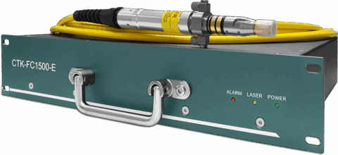
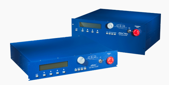
The eDrive Series manages laser diode current and associated DPSS laser functions from a rack-mounted control platform. It is designed for integrating diode arrays, diode-pumped amplifier modules and complete solid-state laser systems. The range includes the 2U eDrive and 4U eDrive Nitro platforms, with air- and water-cooled variants available. Listed standard configurations include 50 A air-cooled CW, 70 A water-cooled CW and 300 A QCW models, while the wider series description references configurations up to 100 A CW. A high-voltage compliance architecture supports multiple diode loads connected in electrical series, subject to confirmation of the selected variant’s rating.
Programmable current and duty-cycle limits work with shutter control, coolant monitoring and safety interlocks to support controlled diode operation. RS-232, RS-485, front-panel controls and hardware trigger connections provide integration options for laboratory, production and automated systems. The 4U Nitro platform can also incorporate optional power, RF, Q-switch and temperature-control functions within its rack housing.
Range features
A high level overview of what this range offers
- CW and QCW operating modes: Supports continuous and pulsed laser diode pumping within the same controller family.
- Up to 300 A QCW output: Accommodates high-current pulsed diode arrays and amplifier pump modules.
- Air- and water-cooled variants: Provides cooling options for different continuous-current and duty-cycle requirements.
- Programmable operating limits: Current and duty-cycle limits help keep the connected diode load within its configured envelope.
- Integrated protection functions: Shutter, coolant and safety interlocks coordinate external protection and laser-enable conditions.
- Positive-edge hardware triggering: Supports synchronization with Q-switches and other laser-system electronics.
- RS-232 and RS-485 interfaces: Enables connection to supervisory controllers and automated test systems.
- LabVIEW compatibility: Supports integration into compatible laboratory and production software environments.
- 19-inch 2U and 4U rack formats: Allows selection according to available rack space and system-integration requirements.
- Optional integrated Nitro functions: Can combine power supplies, RF drivers, Q-switch control and temperature-control options in a 4U housing.
- CE-marked versions available: Supports selection of an appropriately marked configuration where required.
What’s in this range?
All the variants in the range and a comparison of what they offer
Specifications
| Parameter | Air-cooled CW | Air-cooled QCW | Water-cooled CW | Water-cooled QCW |
|---|---|---|---|---|
Output current | 0–50 A | 0–300 A | 0–70 A | 0–300 A |
Current display resolution | 100 mA | 100 mA | 100 mA | 100 mA |
Current accuracy | ±2% | ±2% | ±2% | ±2% |
Output-current noise | 100 mA p-p below 50 A | 100 mA p-p below 50 A | 100 mA p-p below 50 A | 100 mA p-p below 50 A |
Pulse-rate range | 0–100 kHz | 0–100 kHz | 0–100 kHz | 0–100 kHz |
Pulse-rate resolution, 0–100 Hz | 1 Hz | 1 Hz | 1 Hz | 1 Hz |
Pulse-rate resolution, 100 Hz–1 kHz | 10 Hz | 10 Hz | 10 Hz | 10 Hz |
Pulse-rate resolution, 1–50 kHz | 100 Hz | 100 Hz | 100 Hz | 100 Hz |
Pulse-rate accuracy | ±2% | ±2% | ±2% | ±2% |
Pulse-width or timing range | 40 ns–250 µs | 10 µs–500 ms | 40 ns–250 µs | 10 µs–500 ms |
Pulse-width display resolution | 10 ns | 100 ns | 10 ns | 100 ns |
Transition time | — | <40 µs | — | <40 µs |
Trigger input type | Positive edge | Positive edge | Positive edge | Positive edge |
Trigger input signal | TTL or 5 V CMOS | TTL or 5 V CMOS | TTL or 5 V CMOS | TTL or 5 V CMOS |
Minimum trigger-input width | 50 µs | 50 µs | 50 µs | 50 µs |
Trigger-input impedance | 50 Ω | 50 Ω | 50 Ω | 50 Ω |
Trigger output | TTL or 5 V CMOS, 50 Ω driver | TTL or 5 V CMOS, 50 Ω driver | TTL or 5 V CMOS, 50 Ω driver | TTL or 5 V CMOS, 50 Ω driver |
Detailed compliance-voltage range | 0–375 V | 0–375 V | 0–375 V | 0–375 V |
Voltage display resolution | 0.1 V | 0.1 V | 0.1 V | 0.1 V |
Voltage accuracy | ±2% | ±2% | ±2% | ±2% |
Current-monitor scaling | 30 A/V for 100 A models; 60 A/V for 300 A models | 30 A/V for 100 A models; 60 A/V for 300 A models | 30 A/V for 100 A models; 60 A/V for 300 A models | 30 A/V for 100 A models; 60 A/V for 300 A models |
Current-monitor accuracy | ±2% | ±2% | ±2% | ±2% |
Interlock type | Switch contact closure | Switch contact closure | Switch contact closure | Switch contact closure |
Interlock open-circuit voltage | 5 VDC nominal | 5 VDC nominal | 5 VDC nominal | 5 VDC nominal |
Interlock short-circuit current | 60 mA nominal for 2U; 90 mA nominal for 4U Nitro | 60 mA nominal for 2U; 90 mA nominal for 4U Nitro | 60 mA nominal for 2U; 90 mA nominal for 4U Nitro | 60 mA nominal for 2U; 90 mA nominal for 4U Nitro |
Operating temperature | 0–40 °C, non-condensing | 0–40 °C, non-condensing | 0–40 °C, non-condensing | 0–40 °C, non-condensing |
Power input | 100–240 VAC, 50/60 Hz, 15 A maximum | 100–240 VAC, 50/60 Hz, 15 A maximum | 100–240 VAC, 50/60 Hz, 15 A maximum | 100–240 VAC, 50/60 Hz, 15 A maximum |
Rack format | 2U or 4U, 19-inch rack-mount | 2U or 4U, 19-inch rack-mount | 2U or 4U, 19-inch rack-mount | 2U or 4U, 19-inch rack-mount |
The maximum practical pulse rate is typically below 10 kHz and depends on the Q-switch window or current pulse width. Maximum QCW pulse width also varies with output current and internal capacitance. The displayed 10 ns CW timing resolution is rounded internally to the nearest 40 ns.
Variant and range comparison
| Part number | Current rating | Operation | Compliance voltage listed | Rack height | Cooling |
|---|---|---|---|---|---|
ED2C | 50 A | CW | 400 V | 2U | Air-cooled |
ED2C | 70 A | CW | 400 V | 2U | Water-cooled |
ED2P | 300 A | QCW | 400 V | 2U | Air-cooled |
ED2P | 300 A | QCW | 400 V | 2U | Water-cooled |
ED4C | 50 A | CW | 400 V | 4U | Air-cooled |
ED4C | 70 A | CW | 400 V | 4U | Water-cooled |
ED4P | 300 A | QCW | 400 V | 4U | Air-cooled |
ED4P | 300 A | QCW | 400 V | 4U | Water-cooled |
DC2P | 300 A | QCW | 400 V | 2U | Air-cooled |
Rating note: The available product information contains three compliance-voltage expressions: 350 V in the general description, 0–375 V in the detailed electrical data and 400 V in the variant matrix. Confirm the configuration-specific limit before calculating the permissible series diode load.
Current note: The series is described as supporting configurations up to 100 A CW, whereas the standard variant matrix lists 50 A air-cooled and 70 A water-cooled CW models. Requirements above 70 A require confirmation against the exact orderable configuration.
DC2P is included in the range comparison, but no dedicated detailed specification table was available for that model. Mechanical drawings for the 2U and 4U housings, including front and rear layouts, are available in the associated documentation.
FAQs
for eDrive Series laser diode drivers 100A / 300A pulsed & CW
Choose the configuration by separating the continuous-current requirement from the pulsed peak current and thermal-management needs. The listed CW models provide 0–50 A with air cooling and 0–70 A with water cooling, while the QCW models provide 0–300 A with either cooling method. The series is also described as supporting configurations up to 100 A CW, so any requirement above 70 A should be checked against the exact orderable build. Air cooling reduces plant-services requirements, whereas water cooling supports the higher listed CW current and a wider current-dependent QCW duty-cycle envelope. Define the load voltage, peak and average current, pulse width, repetition rate, ambient temperature and available cooling before selecting the model.
For initial calculations, use 0–375 V as the detailed programmable compliance range, but confirm the rating of the exact ordered variant before design release. The product information also presents 350 V as a general figure and 400 V in the variant matrix, creating a configuration or documentation discrepancy that cannot safely be ignored. Compliance voltage provides headroom for the combined forward voltage of series-connected diode arrays, cabling and switching losses; it does not force the load to operate at the maximum voltage. Voltage display resolution is 0.1 V with stated accuracy of ±2%. Calculate the worst-case diode forward voltage at operating current and temperature, add suitable margin and verify the confirmed driver limit against the complete load stack.
The eDrive Series accepts positive-edge TTL or 5 V CMOS triggering through a 50 Ω input with a minimum input width of 50 µs. The pulse-rate setting spans 0–100 kHz, although practical operation is typically below 10 kHz because the allowable rate depends on Q-switch window width for CW timing and current pulse width for QCW operation. The CW timing range is 40 ns–250 µs with 10 ns displayed resolution, internally rounded to 40 ns, while the QCW range is 10 µs–500 ms with 100 ns resolution and a transition time below 40 µs. A TTL or 5 V CMOS trigger output with a 50 Ω driver is provided for downstream timing. Design the synchronization chain around cable termination, propagation delay and combined duty cycle rather than treating each maximum value as simultaneously available.
The protection architecture combines programmable current and duty-cycle limits with shutter control, coolant monitoring and safety interlocks. The interlock input uses switch contact closure with a nominal 5 VDC open-circuit level; nominal short-circuit current is 60 mA for the 2U unit and 90 mA for the 4U Nitro. These functions can prevent operation when external safety or cooling conditions are not satisfied and can help keep the diode array within its configured electrical envelope. They do not replace a system-level risk assessment, an appropriate emergency-stop circuit or independent protection required by the installation. Connect flow, temperature, enclosure and laser-enable conditions into a documented interlock chain, then validate every fault response before enabling full current.
Choose the 2U eDrive when rack height and a modular system architecture are the priority; choose the 4U eDrive Nitro when optional system functions need to be integrated into one housing. Both formats retain the core CW or QCW current control, triggering, interlocks, RS-232 and RS-485 communications, and 19-inch rack mounting. Depending on the build, the Nitro can incorporate options such as a power supply, RF driver, single- or dual-axis Q-switch control and temperature control. This integration can reduce the number of separate chassis and interconnections, but it occupies 4U rather than 2U and requires the options to be defined at the specification stage. Map every external supply, RF, thermal-control and timing function before deciding which functions should remain separate and which should reside in the driver.
Remote integration is supported through RS-232 and RS-485 interfaces, with LabVIEW compatibility and a local front-panel interface on standard configurations. External triggering and timing-synchronization outputs allow deterministic pulse timing to remain in hardware while a host computer manages settings, monitoring and sequencing. OEM and no-front-panel remote-control configurations are also described, which can suit enclosed equipment where local operation is unnecessary. Define command ownership, start-up states, communications-loss behavior and permission to enable current before writing the supervisory software. Keep critical safety interlocks independent of normal software communication, and verify remote readback against the stated ±2% current and voltage accuracy.
The allowable QCW duty cycle must be selected from the peak-current and cooling-specific operating envelope rather than from a single headline percentage. The wider operating envelope is described as reaching up to 20% duty cycle under suitable conditions, while the detailed 2U description identifies 300 A QCW operation at no more than 7% duty cycle for the water-cooled version. Maximum pulse width also depends on output current and internal capacitance, so the 10 µs–500 ms pulse-width range cannot be combined arbitrarily with the 0–100 kHz pulse-rate range. Calculate duty cycle as pulse width multiplied by repetition rate, then compare the result with the correct air- or water-cooled operating chart at the intended peak current. Repeat this check for worst-case cooling, ambient temperature and production tolerances before releasing the driver and diode load for use.