Mirage dynamic IR scene projectors
- Technology
- Dynamic IR scene projectors
- Partner
- Santa Barbara Infrared (SBIR)
The MIRAGE dynamic IR scene projector range comprises the MIRAGE-H and MIRAGE-XL integrated systems for generating real-time infrared scenes in electro-optical test environments. MIRAGE-H is available with a 512 × 512 or 800 × 800 emitter array, while MIRAGE-XL provides a 1024 × 1024 format. Both models use resistive micro-emitter arrays with 48 µm square pixels and real-time per-pixel non-uniformity correction. The architecture combines a Digital Emitter Engine, rack-mounted command and control electronics, and a thermal support subsystem with cooling and power functions.
Applications include hardware-in-the-loop missile-seeker testing, FLIR evaluation, countermeasure simulation and tracking-system testing. DVI, local-memory image uploads and analogue video formats support different scene-generation arrangements, while a Windows interface and remote API provide local or facility-level control. Optional calibration, playback, acceleration and custom collimation functions allow each system to be configured around the radiometric, temporal and optical requirements of the test setup.
Range features
A high level overview of what this range offers
- Resistive micro-emitter array: Generates dynamic infrared scenes while the unit-cell design reduces thermal and electrical crosstalk.
- Multiple array formats: Provides 512 × 512, 800 × 800 and 1024 × 1024 options for different spatial-resolution requirements.
- 48 µm square pixels: Maintains a common emitter pitch across MIRAGE-H and MIRAGE-XL variants.
- 12- to 14-bit delivered grey-scale resolution: Maintains grey-scale performance across fixed or variable unit-under-test integration times.
- Real-time per-pixel correction: Applies an individual non-uniformity correction function to each pixel during operation.
- 20–200 Hz input frame rate: Accommodates static, moderate-rate and fast-changing scene sequences.
- Fast pixel response: Provides a 6.5 ms rise time, reducible to 5.0 ms with the Scene Accelerator upgrade.
- Integrated system architecture: Combines signal processing, power, cooling, calibration hardware and control software in one test system.
- Compact, rugged Digital Emitter Engine: Supports installation on multi-axis motion simulators.
- Automatic and continuous built-in test: Monitors operation and initiates an orderly shutdown when a condition could damage the hardware.
- Windows interface and remote API: Supports direct operator control and integration with facility-control software.
- Flexible scene inputs: Accepts DVI, local-memory and supported analogue sources for live, recorded or locally stored scenes.
What’s in this range?
All the variants in the range and a comparison of what they offer
| Specification | MIRAGE-H | MIRAGE-XL |
|---|---|---|
Emitter array resolution | 512 × 512 pixels or 800 × 800 pixels | 1024 × 1024 pixels |
Pixel size | 48 µm square | 48 µm square |
Effective temperature range, 3–5 µm | 285–675 K; 290–650 K with NUC applied | 285–675 K; 290–650 K with NUC applied |
Effective temperature range, 8–12 µm | 285–500 K; 290–500 K with NUC applied | 285–525 K; 290–500 K with NUC applied |
Thermal resolution, MWIR apparent | Less than 40 mK below 350 K; less than 100 mK above 325 K | Less than 40 mK below 325 K; less than 100 mK above 325 K |
Input frame rate | 20–200 Hz | 20–200 Hz |
Non-uniformity correction | 16-point LUT | 16-point LUT |
Maximum pixels changed per frame | Full frame, stated as 262,144 pixels | Full frame, 1,048,576 pixels |
Pixel rise time, 10–90% | 6.5 ms; 5.0 ms with Scene Accelerator upgrade | 6.5 ms; 5.0 ms with Scene Accelerator upgrade |
Dead pixels | Less than 0.5% | Less than 0.5% |
Digital Emitter Engine size | 14.5 in diameter × 13.5 in length | 14.5 in diameter × 13.5 in length |
Digital Emitter Engine weight | 54 lb | 54 lb |
Input scene data | DVI and local-memory image upload | DVI and local-memory image upload |
FAQs
for Mirage dynamic IR scene projectors
Select MIRAGE-H when a 512 × 512 or 800 × 800 array satisfies the scene and unit-under-test requirements, and select MIRAGE-XL when a 1024 × 1024 format is needed. Both variants use 48 µm pixels, accept 20–200 Hz scene input and have a Digital Emitter Engine measuring 14.5 in in diameter by 13.5 in in length at 54 lb. This keeps the stated mechanical and temporal baseline broadly consistent, making spatial resolution the principal differentiator. In practice, compare the array format with the intended field of view, projected target size, collimator focal length and detector sampling. The projector and its optics should be specified as a complete optical chain.
The projectors cover stated operating ranges in the 3–5 µm MWIR and 8–12 µm LWIR bands. Both variants provide an MWIR effective temperature range of 285–675 K, with a non-uniformity-corrected range of 290–650 K. In LWIR, MIRAGE-H covers 285–500 K and MIRAGE-XL covers 285–525 K, while both specify 290–500 K with correction applied. The corrected span is the more relevant working range when uniformity-controlled output is required. Engineers should map every required apparent-temperature point to the selected waveband and corrected operating range before finalising the system configuration.
The systems accept input frame rates from 20 to 200 Hz, making them suitable for a range of dynamic hardware-in-the-loop sequences. At 200 Hz, each frame occupies 5 ms, compared with the standard pixel rise time of 6.5 ms. The Scene Accelerator upgrade reduces the stated rise time to 5.0 ms, aligning it more closely with the maximum-rate frame period. Large temperature transitions may still require careful analysis because emitter response, unit-under-test integration time and scene timing all affect the observed stimulus. End-to-end timing should therefore be validated with representative scene content rather than from frame rate alone.
Non-uniformity correction is applied to each pixel in real time, with the specifications identifying a 16-point lookup table. An optional Calibration Radiometry System compares individual emitter-pixel output with a pair of blackbody references and automates the collection of correction data. This provides a controlled basis for correcting spatial variations across the array and over its dynamic range. Calibration can be performed within the test facility or incorporated as part of the supplied system configuration. Absolute radiometric accuracy and recalibration intervals are not specified, so users should define them through their uncertainty budget, verification procedure and quality requirements.
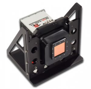
Each system comprises a Digital Emitter Engine, command and control electronics, and a thermal support subsystem. The command and control electronics are PC-based and installed in a rack configuration, while the thermal subsystem includes power supplies, a refrigerated chiller and an ion-pump controller. The Digital Emitter Engine weighs 54 lb and measures 14.5 in in diameter by 13.5 in in length, with a fibre-optic scene-data receiver and a kinematic optical interface. Installation planning should therefore include rack space, structural support, cooling connections, cable and hose routing, and access for optical alignment. Electrical-load and coolant-capacity values must be confirmed before completing the facility design.
The primary scene-data paths are DVI and local-memory image upload, while RS-170, NTSC and PAL analogue video inputs are also supported. DVP2 and DDO2 are identified within the wider range and should be confirmed for the selected model and configuration. A Windows graphical interface provides system setup, sequencing, operational status and built-in-test reporting. A remote application programming interface allows the projector to be controlled from facility software rather than solely from the local workstation. Where repeatable prerecorded sequences are needed, the optional image playback system can capture DVI data to disk and replay selected sequences in real time.
The main options are the Calibration Radiometry System, real-time image playback, custom collimators and the Scene Accelerator upgrade. The calibration system is relevant where users need facility-controlled non-uniformity correction based on blackbody references. Image playback supports the capture, storage and repeated DVI playback of test sequences, while the accelerator reduces the stated pixel rise time from 6.5 to 5.0 ms. A custom collimator should be specified around the required waveband, field of view, aperture, focal length and unit-under-test pupil geometry. These options should be selected from the radiometric error budget, timing model and optical interface requirements rather than treated as general-purpose accessories.
Shipment outside the United States requires an export licence, so licensing should be incorporated into the procurement schedule. A fixed ordering code is not defined for the range because the required model, emitter format, optics, calibration arrangement and optional subsystems depend on the application. The technical specification should identify the required resolution, waveband, corrected temperature range, frame rate, optical interface, playback functions and facility constraints. Export classification, destination approval and configuration-specific documentation should be confirmed before placing the order. Final interface, utility and dimensional information should also be obtained before the test-cell design is frozen.