Taurus-R specialty positioner
- Technology
- Pan and tilt positioners
- Partner
- Quickset Defense Technologies, LLC
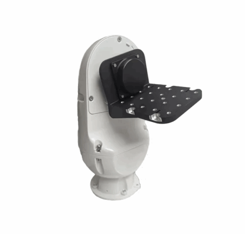
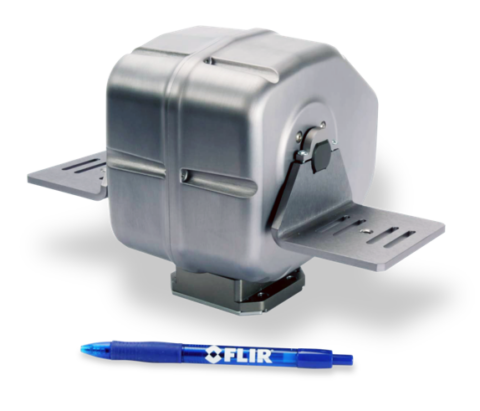
The Taurus-R is a mobile pan-and-tilt positioner for combining radar, EO/IR cameras and complementary sensor payloads within one assembly. It is intended for engineers integrating surveillance systems on ground vehicles, trailers, towers or fixed structures. The balanced payload rating is up to 68 kg, with an RF pass-through turret for a top-mounted radar or another independently positioned device. Motion capability covers continuous 360° pan and 180° tilt, with commanded speeds from 0.005 to 60°/s depending on the axis and payload balance.
Serial and 10/100 Ethernet interfaces support motion control and sensor communications, while slip-ring options accommodate HD-SDI or IP data paths. A thermostatic heater, marine IP67 configuration, and health and usage monitoring support exposed installations and planned maintenance. The Taurus-R is designed for periodic movement, so constant-motion applications require a separate duty-cycle assessment.
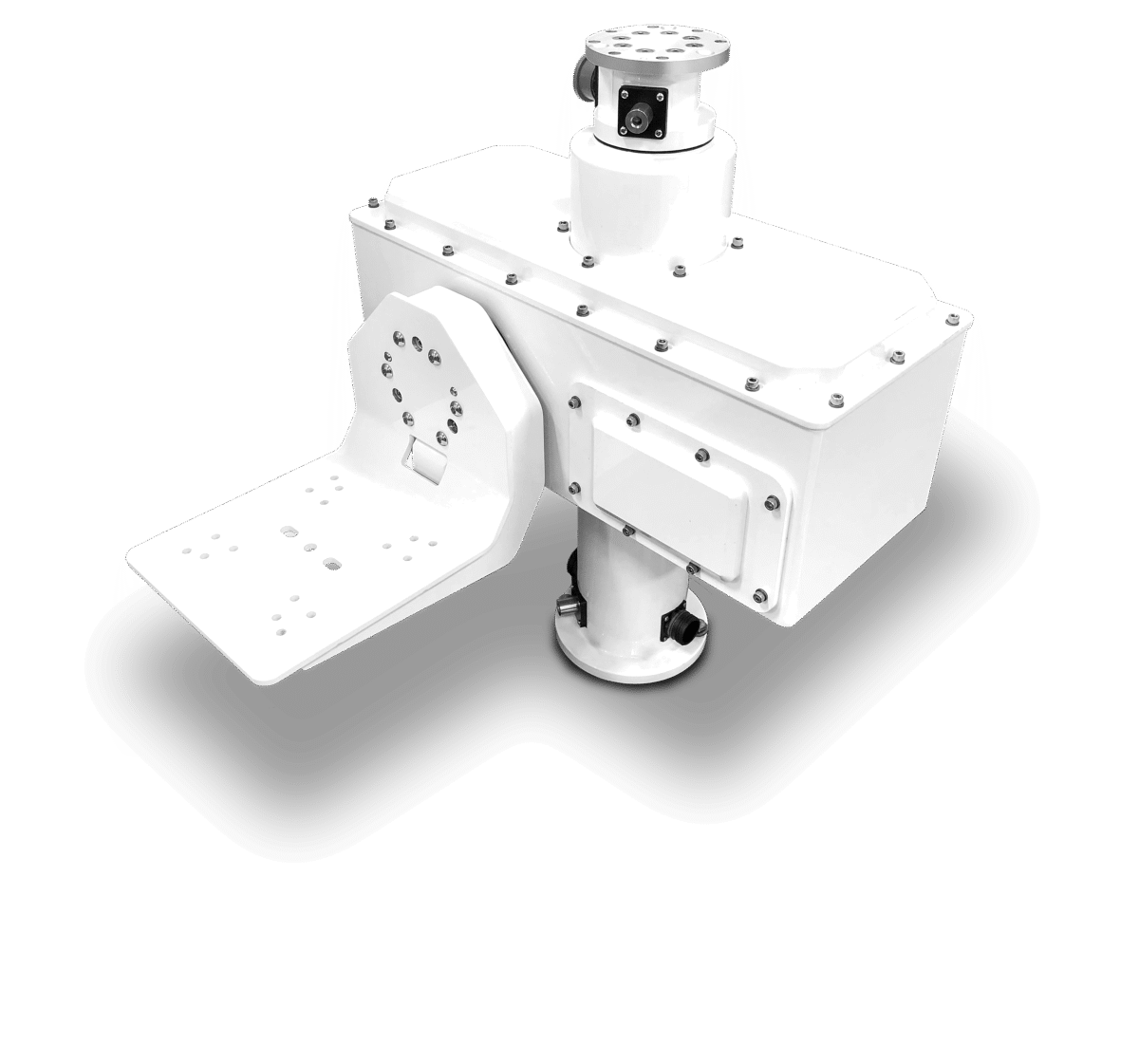
Range features
A high level overview of what this range offers
- Balanced payload capacity up to 68 kg: Accommodates combined radar, camera, and ancillary sensor assemblies.
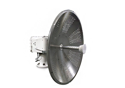
- RF pass-through turret: Supports a top-mounted radar or another independently positioned payload.
- Continuous 360° pan rotation: Prevents pan-axis cable wrap through an internal slip-ring arrangement.
- 180° tilt range: Provides movement from −90° to +90°.
- Speed range from 0.005 to 60°/s: Supports slow scanning and faster repositioning, subject to payload conditions.
- Optical encoder feedback: Provides 0.01° readout and 0.05° repeatability.
- HD-SDI and IP configuration options: Support uncompressed video or Ethernet-connected sensor architectures.
- Serial and Ethernet control interfaces: Enable integration through RS232, RS422, RS485, or 10/100 Base-T.
- Configurable payload communications: Provide serial, TTL, IP, and virtual serial connection options.
- Native PTZ and Pelco-D protocols: Support integration with different control environments.
- Health and usage monitoring: Tracks runtime, temperature, and operating status for maintenance planning.
- Thermostatically controlled heater: Supports temperature management during cold-weather operation.
- Marine IP67 configuration: Provides an ingress-protected option for exposed and marine installations.
- MIL-STD-810H vibration and shock references: Support evaluation for vehicle-mounted and mobile applications.
Downloads
for Taurus-R specialty positioner
What’s in this range?
All the variants in the range and a comparison of what they offer
| Specification | Value |
|---|---|
Product type | Mobile pan-and-tilt positioner |
Installation types | Static or mobile |
Supported sensors | Radar antennas, visible and IR cameras, illuminators, laser rangefinders, communications antennas, and acoustic devices |
Balanced load capacity | Up to 150 lb / 68 kg |
Operating voltage | 24 V DC ±4 V DC |
Electrical current | 6.5 A at power-on; 8.6 A in motion; 0.5 A in standby |
Pan-axis range | 360° continuous rotation through slip ring |
Pan-axis speed | 0.005 to 60°/s, dependent on payload |
Tilt-axis range | 180° total, ±90° |
Tilt-axis speed | 0.005 to 60°/s with a balanced payload |
Internal heater | Thermostatically controlled; on at 0°C and off at 5°C |
Operating temperature | −32°C to +55°C |
Rotational limits | Fixed tilt hard limit; adjustable soft limits on both axes |
Position feedback | Optical encoders with 0.01° readout |
Repeatability | 0.05° |
Motor and drive type | Stepper |
Velocity control | 10-bit linear response with direct degrees-per-second commands |
Positioner communications | RS232, RS422, RS485, and 10/100 Base-T Ethernet |
Sensor communications | RS232, RS422, and Ethernet pass-through |
Payload communication ports | Four configurable serial ports, two TTL ports, and one IP port; virtual serial connection over a single IP link |
Control protocols | Native PTZ protocol and Pelco-D |
Video and data options | Dual HD-SDI output or IP pass-through configuration; IP arrangement supports up to four 10/100 Ethernet devices |
Geospatial functions | Geo-positioning and geo-targeting |
Connector specification | Military-specification grade connectors on all configurations |
Load connector interfaces | Two military-specification connectors on each tilt-axis platform |
Ingress protection | IP67 on the marine configuration |
Housing material | 6061-T6 aluminium |
Additional construction materials | Stainless-steel hardware and permanently sealed radial ball bearings |
Standard finish | White powder coating over a chromate-treated surface for corrosion resistance |
Alternative finishes | Additional colours and CARC finishes available on request |
Positioner weight | 94 lb / 43 kg |
Commissioning equipment | 6 ft test cable and software included |
Duty cycle | Designed for periodic movement; constant-motion use requires an application-specific assessment |
Vibration | MIL-STD-810H, Method 514.8, Procedure I |
Mechanical shock | MIL-STD-810H, Method 516.8, Procedure I |
FAQs
for Taurus-R specialty positioner
Yes, the Taurus-R combines a pan-and-tilt payload platform with an RF pass-through turret for a top-mounted radar or another independently positioned payload. Its balanced load rating is up to 68 kg for static and mobile installations, while two military-specification connectors are provided on each tilt-axis platform for sensor interfaces. Depending on the slip-ring configuration, the system can route two HD-SDI channels or support IP-connected devices over 10/100 Ethernet. In practice, the complete payload must be balanced around the tilt axis, and the radar, video, and communications arrangement should be fixed before mechanical and cable design begins.
The positioner covers 360° continuous pan and 180° tilt, equivalent to −90° to +90°, with speeds from 0.005 to 60°/s. Pan speed depends on the payload, and the 60°/s tilt value applies to a balanced load. Optical encoder feedback provides 0.01° readout with 0.05° repeatability, while 10-bit linear velocity control and direct degrees-per-second commands support controlled tracking profiles. These figures suit slow scanning and faster repositioning, although balancing, command update rate, and structural stiffness will influence realised performance. The unit is intended for periodic movement, so applications requiring constant motion need a duty-cycle review before selection.
Specify a nominal 24 V DC supply with an allowed tolerance of ±4 V DC. The listed currents are 6.5 A at power-on, 8.6 A in motion, and 0.5 A in standby, so the supply, protection devices, and conductors should accommodate the 8.6 A operating demand as well as start-up transients. Cable length, connector resistance, and mobile-platform voltage variation should be assessed against the resulting 20–28 V DC input window. Military-specification connectors are used across the configurations, and a 6 ft test cable with software is included for commissioning. Confirm whether connected sensors require a separate power allocation when preparing the total system power budget.
Control can be implemented through RS232, RS422, RS485, or 10/100 Base-T Ethernet. The unit supports a native PTZ protocol and Pelco-D, while sensor-side connectivity includes RS232, RS422, and Ethernet pass-through. The payload interface includes four configurable serial ports, two TTL ports, and one IP port, together with virtual serial communication over a single IP connection. This gives integrators several routes for connecting cameras, radar, illuminators, and ancillary devices without adding a separate motion controller. Before completing the interface control document, confirm signal levels, port allocation, baud rates, and whether stabilisation or geo-targeting data will use serial or Ethernet transport.
For mobile and exposed installations, the Taurus-R combines an operating range of −32°C to +55°C with thermostatically controlled internal heating. The heater switches on at 0°C and off at 5°C, reducing the need for a separate enclosure-heating circuit. Vibration is referenced to MIL-STD-810H Method 514.8 Procedure I, and mechanical shock to Method 516.8 Procedure I; the marine configuration is rated to IP67. The housing uses 6061-T6 aluminium, stainless-steel hardware, and permanently sealed radial ball bearings. In practice, specify the marine configuration when ingress protection is required and verify that the selected finish, connectors, and mounting structure suit the site’s corrosion and vibration exposure.
Choose the slip-ring arrangement around the intended sensor data architecture. One configuration carries two HD-SDI channels alongside the co-located radar path, which is appropriate when uncompressed real-time video must pass through the rotating assembly. An alternative IP configuration supports pass-through connectivity for up to four 10/100 Ethernet devices, enabling networked sensors to share the positioner installation. These options should not be treated as automatically interchangeable after integration because connector selection, internal routing, and external cabling depend on the ordered configuration. Establish the number of video streams, Ethernet devices, required bandwidth, and radar path before releasing the mechanical design or procurement specification.
The 68 kg rating applies to a balanced payload, so mass alone is not enough to confirm suitability. The centre of gravity, tilt-axis moment, cable forces, and dynamic loads from a vehicle or tower installation must be considered alongside the positioner’s 43 kg own weight. Adjustable soft limits are available on both axes, while tilt also has a fixed hard limit; these controls help prevent the payload or cables from entering restricted zones. The architectural drawing should be used to verify mounting interfaces and clearance without estimating dimensions from product photographs. Because the stated duty is periodic movement, continuous scanning or persistent tracking should be reviewed as a separate application condition.
Health and usage monitoring provides runtime, temperature, and status information that can be used to plan inspections and maintenance. This is useful on towers, trailers, and ground vehicles where access may be limited and unexpected downtime can affect the wider sensor system. The monitored information can help teams relate service intervals to actual use rather than calendar time alone, particularly where motion frequency and ambient temperature vary between deployments. It should be integrated into an agreed maintenance process with defined alert thresholds, data-review responsibilities, and escalation actions. Confirm the required logging, communications, and service workflow during system design so the information can be used by the operating organisation.