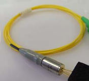
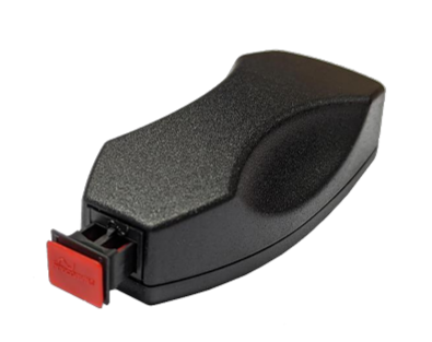
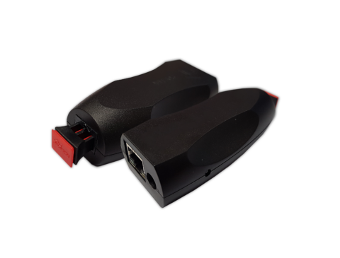
FT1M2HAR 650 nm 10-250 MBd 50-80 m RedLink® POF Horizontal Transmitter
- Technology
- Plastic Optical Fibre (POF) components
- Partner
- Firecomms
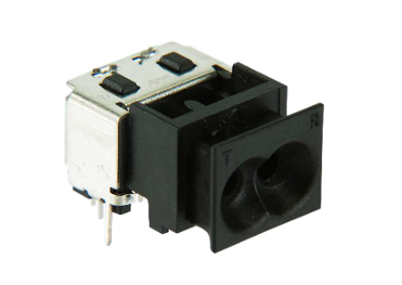
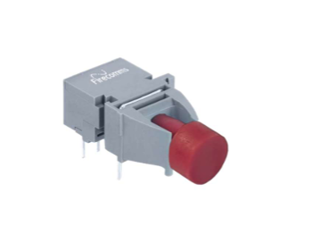
The FT1M2HAR is a horizontal 650 nm transmitter for RedLink® plastic optical fibre connections operating from 10 to 250 MBd. Its stated 50–80 m range can suit medium-distance signal paths in machinery, production cells and distributed control equipment, provided the complete link budget is satisfied. The horizontal format is intended for PCB layouts that route the fibre connection parallel to the board. When paired with a compatible receiver and suitable POF, the optical link can support electrical separation between communicating circuits without using conductive data cabling. System designers should calculate the complete optical and timing budgets rather than treating the maximum distance as independent of data rate, fibre attenuation or connector losses. The FT1M2HAR can therefore be considered where visible-wavelength POF, board orientation and signalling rates up to 250 MBd are key selection criteria.
Range features
A high level overview of what this range offers
- 650 nm optical transmission: Supports visible-wavelength plastic optical fibre link designs.
- 10–250 MBd operating range: Covers multiple serial signalling rates with one transmitter type.
- 50–80 m stated link range: Can support machine-level and cabinet-to-cabinet connections when the complete optical budget is met.
- Horizontal RedLink® format: Allows the fibre connection to run parallel to the PCB in suitable enclosure layouts.
- POF transmission medium: Can support galvanic separation and resistance to electromagnetic interference as part of a correctly designed optical link.
- Dedicated transmitter function: Allows the receiver, fibre and connector system to be selected around the application requirements.
Downloads
for FT1M2HAR 650 nm 10-250 MBd 50-80 m RedLink® POF Horizontal Transmitter
What’s in this range?
All the variants in the range and a comparison of what they offer
| Specification | Value |
|---|---|
Part number | FT1M2HAR |
Product series | RedLink® |
Product type | POF optical transmitter |
Optical wavelength | 650 nm |
Signalling rate | 10–250 MBd |
Stated link distance | 50–80 m; final reach depends on the complete optical link |
Transmission medium | Plastic optical fibre, POF |
Connector orientation | Horizontal |
FAQs
for FT1M2HAR 650 nm 10-250 MBd 50-80 m RedLink® POF Horizontal Transmitter
Yes, 250 MBd is within the declared 10–250 MBd signalling range. At 250 MBd, one symbol occupies only 4 ns, so transmitter drive quality, fibre behaviour, receiver bandwidth, jitter and PCB signal integrity all consume part of the available timing margin. The rated signalling range does not by itself demonstrate compliance with a particular communication protocol or coding scheme. Engineers should verify the end-to-end eye opening and error performance with the intended receiver, POF length and connector set under worst-case operating conditions.
The 50–80 m figure should be treated as a system-level design range rather than an unconditional cable-length guarantee. Achievable reach depends on optical launch level, receiver sensitivity, POF attenuation at 650 nm, connector insertion loss, bends, contamination, temperature and ageing. A 50 m installation will generally provide more optical margin than an 80 m installation assembled from the same components, but the actual margin must be calculated for the selected link. For an 80 m target, include production tolerances and maintenance-related losses rather than validating only a short laboratory sample.
The horizontal format places the optical connection so that the fibre exits broadly parallel to the PCB rather than vertically away from it. This can suit low-profile housings, front-panel routing and card layouts where overhead clearance is limited, but it also makes the board-edge position and fibre path important. The layout should reserve space for the connector body, mating plug, strain relief, insertion access and the permitted POF bend radius. Before releasing the PCB, verify the controlled footprint, keep-out areas and mechanical tolerance stack rather than estimating them from the housing orientation.
At 650 nm, the transmitter is intended for visible-light plastic optical fibre links used in short- and medium-range communications. Because the data path is optical, a complete link can provide galvanic separation between the transmitter and receiver circuits when no conductive signal path bridges the isolation boundary. It can also avoid electromagnetic pickup on the communication medium, although power, grounding, shielding and enclosure design still require separate attention. For a 50–80 m installation, fibre attenuation and connector losses remain central to the optical budget, so POF does not remove the need for worst-case link analysis.
Select a receiver that supports 650 nm POF operation and the required symbol rate within the transmitter’s 10–250 MBd range. Receiver sensitivity, maximum optical input, logic polarity and electrical output must suit the protocol while leaving adequate optical margin across the intended 50–80 m path. Fibre construction, core size, numerical aperture, connector compatibility and attenuation at 650 nm should be assessed as a complete system rather than selected independently. Build the budget from the transmitter output through every fibre and connector loss to the receiver threshold, retaining margin for temperature, ageing, contamination and production spread.
Do not assume that the transmitter can be connected directly to any microcontroller or FPGA output without interface checks. The required input topology, drive amplitude or current, supply arrangement, threshold levels, input capacitance and edge-rate limits must all match the selected driver circuit. At 250 MBd, the 4 ns symbol period leaves little tolerance for slow edges, ringing or pulse-width error, so PCB routing, return paths and local decoupling become part of the optical link design. Prototype measurements should confirm the electrical waveform at the transmitter pins and the received optical eye under the intended operating conditions.
Operation below 10 MBd or with a static DC state should not be assumed from a product range defined as 10–250 MBd. Some transmitter and receiver architectures depend on transition density, duty cycle or internal bias behaviour, so a valid high or low state may not be preserved indefinitely outside the qualified signalling range. If the application includes long idle periods, low-frequency PWM or unusual line coding, test those exact patterns rather than validating only a balanced high-speed data stream. Where continuous DC transmission is required, select a device whose operating range explicitly includes DC or obtain application-specific confirmation before design release.