CT-0155TBP-MB5L-E 1310 nm FP/1550 nm PIN 20 km 155 Mb/s SFP Bi-Di Transceiver w. DDMI
- Technology
- Optical transceivers
- Partner
- Coretek
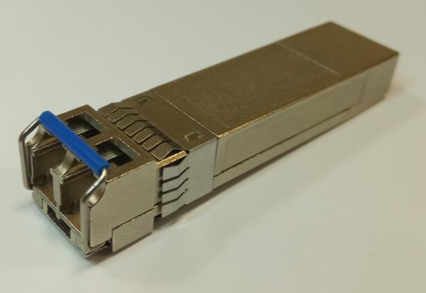
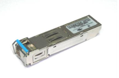
The CT-0155TBP-MB5L-E is a compact optical module for bidirectional links over single-mode fibre. It transmits at a nominal 1310 nm and receives at a nominal 1550 nm, allowing both directions to share one fibre strand when paired with complementary wavelength optics. Its 125 to 155 Mb/s NRZ data-rate range supports Fast Ethernet and selected FDDI, ATM, SONET OC-3 and SDH STM-1 applications. Typical uses include access equipment, optical-electrical interface conversion and intermediate-reach fibre connections of up to 20 km. The 3.3 V module follows the SFP MSA and uses a single LC optical connector. SFF-8472 digital diagnostics are available through an I²C serial interface for host-side module supervision. The −40°C to +85°C operating case temperature range supports equipment exposed to extended temperature variation.
Range features
A high level overview of what this range offers
- 1310 nm FP transmitter and 1550 nm PIN receiver: Supports wavelength-separated transmission and reception through one LC optical port.
- 20 km single-mode fibre reach: Provides an intermediate-reach option for compatible optical links.
- 125 to 155 Mb/s NRZ operation: Covers Fast Ethernet and selected FDDI, ATM, OC-3 and STM-1 data rates.
- 18 dB worst-case optical power budget: Combines −14 to −8 dBm launch power with receiver sensitivity of −32 dBm or better before path losses and system margin.
- SFF-8472 digital diagnostics: Provides identification and diagnostic access through the host I²C interface.
- Single LC Bi-Di connection: Enables transmit and receive traffic to share one single-mode fibre strand.
- 3.1 to 3.5 V operating supply: Integrates with compatible 3.3 V SFP host interfaces.
- −40°C to +85°C case operation: Supports equipment intended for extended-temperature environments.
- SFP MSA interface: Uses the standard SFP mechanical format, electrical interface and pin assignment.
- Class 1 optical design: Supports laser-safety integration in accordance with EN 60825-1.
- RoHS-compliant, lead-free construction: Supports restricted-substance requirements for electronic assemblies.
Downloads
for CT-0155TBP-MB5L-E 1310 nm FP/1550 nm PIN 20 km 155 Mb/s SFP Bi-Di Transceiver w. DDMI
What’s in this range?
All the variants in the range and a comparison of what they offer
Specifications
| Category | Parameter | Symbol | Specification |
|---|---|---|---|
General | Product type | — | SFP Bi-Di optical transceiver |
General | Data rate | — | 125 to 155 Mb/s, NRZ |
General | Link distance | — | 20 km |
General | Fibre type | — | Single-mode fibre; optical power referenced to 9/125 µm fibre |
General | Optical connector | — | Single LC |
General | Nominal supply | VCC | 3.3 V |
General | Operating supply range | VCC | 3.1 to 3.5 V |
General | Electrical data interface | — | AC/AC differential |
General | Signal-detect output | — | TTL |
General | Digital diagnostics | — | SFF-8472 interface via I²C |
Environmental | Operating case temperature | TA | −40°C to +85°C |
Absolute maximum | Storage temperature | TS | −40°C to +85°C |
Absolute maximum | Supply voltage | VCC | 0 to 6 V |
Absolute maximum | Data input voltage | — | 0 V to VCC |
Transmitter | Emitter type | — | FP laser diode |
Transmitter | Nominal wavelength | — | 1310 nm |
Transmitter | Centre wavelength | λc | 1260 nm minimum, 1310 nm typical, 1360 nm maximum |
Transmitter | Average optical output power | Po | −14 to −8 dBm, measured into 9/125 µm single-mode fibre |
Transmitter | Extinction ratio | ER | 8.2 dB minimum |
Transmitter | RMS spectral width | Δλ | 4 nm maximum |
Transmitter | Optical rise time, 10% to 90% | tr | 2.0 ns maximum |
Transmitter | Optical fall time, 10% to 90% | tf | 2.0 ns maximum |
Transmitter | Output eye | — | IEEE 802.3ah and ITU-T G.957 |
Receiver | Detector type | — | PIN photodiode |
Receiver | Nominal wavelength | — | 1550 nm |
Receiver | Operating wavelength | λ | 1480 to 1600 nm |
Receiver | Maximum optical input power | Pmax | −3 dBm |
Receiver | Sensitivity | Pmin | −32 dBm or better at 155 Mb/s, 2²³−1 PRBS and BER below 10⁻¹⁰ |
Receiver | Optical return loss | ORL | 14 dB minimum |
Receiver | Loss-of-signal asserted level | PA | −45 dBm |
Receiver | Loss-of-signal deasserted level | PD | PA + 0.5 dB to −31 dBm |
Receiver | Loss-of-signal hysteresis | PD − PA | 0.5 to 4 dB |
Electrical | Transmitter supply current | ICCT | 200 mA maximum |
Electrical | Receiver supply current | ICCR | 100 mA maximum |
Electrical | Data input voltage swing | VID | 400 to 1600 mV |
Electrical | Receiver differential output voltage | VOD | 0.4 to 1.3 V |
Electrical | TX Disable low input | VIL | 0 to 0.8 V |
Electrical | TX Disable high input | VIH | 2.0 V to VCC |
Electrical | TX Fault low output | VOL | 0 to 0.8 V |
Electrical | TX Fault high output | VOH | 2.0 V to VCC |
Electrical | RX LOS low output | VOL | 0 to 0.8 V |
Electrical | RX LOS high output | VOH | 2.0 V to VCC |
Electrical | MOD-DEF(1) and MOD-DEF(2) low level | VIL | −0.6 V to 0.3 × VCC |
Electrical | MOD-DEF(1) and MOD-DEF(2) high level | VIH | 0.7 × VCC to VCC + 0.5 V |
Timing | TX Disable assertion time | t_off | 10 µs maximum |
Timing | TX Disable negate time | t_on | 1 ms maximum |
Timing | Initialisation time, including TX Fault reset | t_init | 300 ms maximum |
Timing | Fault-to-TX Fault assertion time | t_fault | 100 µs maximum |
Timing | TX Disable reset-start time | t_reset | 10 µs maximum |
Timing | RX LOS assertion time | tA,RX_LOS | 100 µs maximum |
Timing | RX LOS deassertion time | tD,RX_LOS | 100 µs maximum |
Standards | SFP interface | — | SFP MSA |
Standards | Digital diagnostic interface | — | SFF-8472 |
Standards | Ethernet reference | — | IEEE 802.3ah 100BASE-BX10-U |
Standards | Additional protocol references | — | FDDI PMD and ATM |
Standards | Reliability reference | — | Telcordia GR-468-CORE |
Standards | Eye safety | — | Class 1, EN 60825-1 |
Standards | EMC references | — | FCC Class B and CENELEC EN 55022 (CISPR 22) |
Materials | Restricted substances | — | RoHS-compliant and lead-free |
SFP pin assignment
| Pin | Signal | Function |
|---|---|---|
1 | VeeT | Transmitter ground |
2 | TX Fault | Transmitter fault indication |
3 | TX Disable | Transmitter disable; active high or open |
4 | MOD-DEF(2) | Two-wire serial interface data |
5 | MOD-DEF(1) | Two-wire serial interface clock |
6 | MOD-DEF(0) | Grounded inside the module |
7 | Rate Select | Not connected |
8 | LOS | Receiver loss-of-signal indication |
9 | VeeR | Receiver ground |
10 | VeeR | Receiver ground |
11 | VeeR | Receiver ground |
12 | RD− | Inverted received-data output |
13 | RD+ | Non-inverted received-data output |
14 | VeeR | Receiver ground |
15 | VccR | Receiver power supply |
16 | VccT | Transmitter power supply |
17 | VeeT | Transmitter ground |
18 | TD+ | Non-inverted transmitter-data input |
19 | TD− | Inverted transmitter-data input |
20 | VeeT | Transmitter ground |
FAQs
for CT-0155TBP-MB5L-E 1310 nm FP/1550 nm PIN 20 km 155 Mb/s SFP Bi-Di Transceiver w. DDMI
The remote unit must use the complementary wavelength direction, transmitting near 1550 nm and receiving near 1310 nm. Two identical CT-0155TBP-MB5L-E modules should not be installed at opposite ends because both would transmit at 1310 nm while listening in the 1550 nm receive band. The paired device should also support the same 125 to 155 Mb/s NRZ rate, single-mode fibre, single-LC Bi-Di architecture and adequate optical budget. Connector condition, path loss and receiver overload must be included in the pairing review. Select an opposite-wavelength SFP with compatible host signalling and timing rather than matching only the nominal reach.
The worst-case transmitter-to-receiver budget is 18 dB, calculated from the minimum launch power of −14 dBm and the receiver sensitivity limit of −32 dBm. This is the starting budget before connector loss, splice loss, fibre attenuation, ageing, temperature effects and engineering margin are deducted. Sensitivity is specified at 155 Mb/s using a 2²³−1 PRBS with BER below 10⁻¹⁰, so different test conditions may not produce the same result. The receiver maximum input level is −3 dBm, which must also be respected on short or unusually low-loss paths. A 20 km design should therefore be accepted only after a complete end-to-end loss calculation and measured optical-power verification.
The module covers 125 to 155 Mb/s NRZ and is intended for Fast Ethernet, FDDI, ATM/SONET OC-3 and SDH STM-1 applications. It identifies IEEE 802.3ah 100BASE-BX10-U, FDDI PMD and ATM compatibility, while the output eye is specified against IEEE 802.3ah and ITU-T G.957. This rate coverage does not guarantee that every host port will accept every listed protocol because the host controller, clocking, framing and electrical interface must match the intended service. The optical module uses an AC/AC differential data interface and the standard SFP pin arrangement. Both the line rate and the host equipment’s protocol support should be verified before qualification.
The host should provide a regulated 3.3 V rail that remains within 3.1 to 3.5 V at the module pins. Maximum transmitter and receiver currents are 200 mA and 100 mA respectively; if both maxima occur together, the supply allowance is 300 mA, or approximately 1.05 W at 3.5 V. That calculated figure is a conservative host-budget estimate rather than a stated module power rating. The operating case range is −40°C to +85°C, but the equipment must still control local airflow, cage heating and neighbouring component dissipation. The 0 to 6 V absolute maximum supply range is a survival limit and must not be treated as an operating range.
Digital diagnostics are accessed through the SFF-8472 two-wire interface on MOD-DEF(1) and MOD-DEF(2), with MOD-DEF(0) grounded inside the module. The host can use this I²C path for identification and diagnostic access, while TX Fault, TX Disable and RX LOS provide the principal hardware control and alarm functions. TX Disable is active high, and the transmitter is also disabled when the input is left open, which should be considered during start-up and fault handling. The maximum initialisation period, including TX Fault reset, is 300 ms, while the TX Disable negate time is up to 1 ms. Host firmware should allow for these intervals before declaring a failed module or optical link.
The transmit input accepts a 400 to 1600 mV differential swing, while the receiver provides a 0.4 to 1.3 V differential output. TD+ and TD− are the transmit pair on pins 18 and 19, and RD+ and RD− are the receive pair on pins 13 and 12. The data path is specified as an AC/AC differential interface, so the host design should use the required coupling, termination and controlled-impedance routing approach for an SFP port. Differential pairs should be kept short, balanced and isolated from noisy power or clock nodes, with supply filtering positioned close to the cage. Signal-integrity validation should include eye testing at the intended 125 to 155 Mb/s operating rate.
The module is designed as a Class 1 optical product compliant with EN 60825-1 and is identified as RoHS-compliant and lead-free. It also follows the SFP MSA and lists EMC design objectives including FCC Class B and CENELEC EN 55022, equivalent to CISPR 22. These statements do not remove the need to test the completed equipment because emissions, immunity, earthing, enclosure design and cable routing depend on the host system. The optical characteristics are described as being evaluated in line with Telcordia GR-468-CORE. System-level EMC, electrical safety and laser-safety verification should therefore remain part of the equipment qualification plan.