PMA1101 – Railway DC/AC Inverter 510Vdc to 230Vac / 50 Hz
- Technology
- Enclosed power supplies
- Partner
- Acal BFi
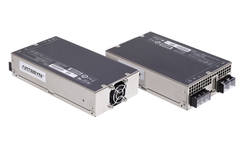
The PMA1101 railway inverter is a fanless DC/AC power converter for installation in railway rolling stock. It operates from a 400–600 VDC input range, with a nominal input of 510 VDC, and produces a single-phase 230 VAC output. Its pure sine-wave output has less than 2% total harmonic distortion, supporting AC distribution systems that require a controlled waveform. The inverter provides 3,000 VA nominal apparent power, while operation up to 3,600 VA is available subject to the defined thermal derating limits. A galvanically isolated control input allows the AC output to be switched remotely, while a potential-free relay and green status LED indicate whether the output is within its operating range. The fanless cooling arrangement avoids internal fan servicing, although the specified mounting orientation and cooling clearances must be maintained. Electrical, environmental and vibration requirements are defined for rolling-stock installations, including EN 50155, EN 50121-3-2 and EN 61373 Category 1, Class B.
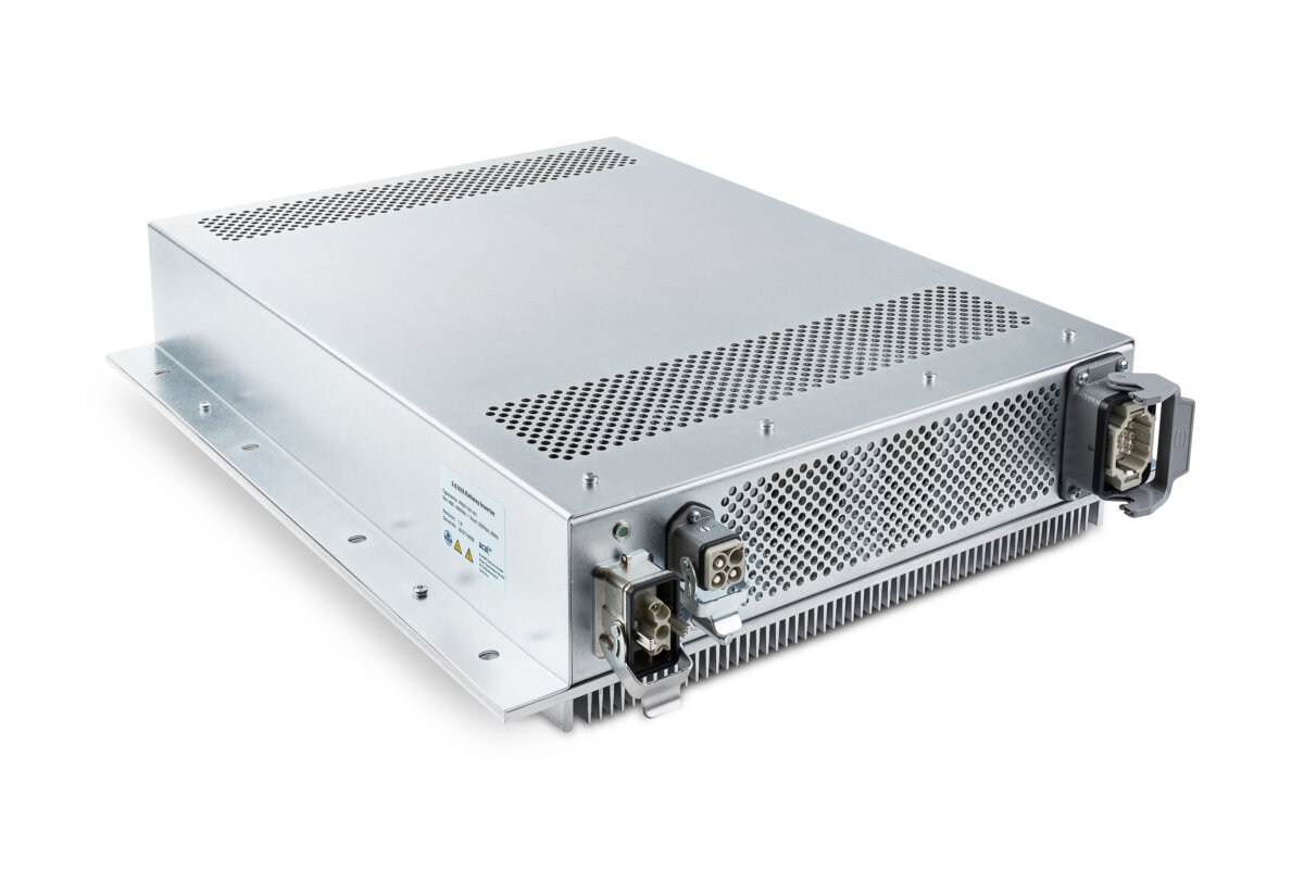
The PMA1101 is a railway DC/AC inverter for converting a nominal 510 VDC rolling-stock supply into a galvanically isolated single-phase 230 VAC, 50 Hz output. It is designed for onboard passenger and auxiliary AC loads such as socket outlets, USB charging systems and comparable equipment.
Its fanless construction, pure sine-wave output with less than 2% THD and efficiency above 93% support use in rail vehicles where low maintenance, waveform quality and controlled thermal behaviour are important. The unit is intended for protected installation areas and is specified against key rolling-stock requirements including EN 50155, EN 50121-3-2 and EN 61373 Category 1, Class B.
Range features
A high level overview of what this range offers
- 400–600 VDC input range: Supports a nominal 510 VDC railway power supply.
- 230 VAC, 50 Hz single-phase output: Provides a standard onboard AC supply for passenger-facing loads.
- 3,000 VA nominal output: Delivers rated continuous apparent power for normal operation.
- Up to 3,600 VA maximum output: Supports higher-power operation within the stated thermal limits.
- Pure sine-wave output with THD below 2%: Supplies sensitive AC equipment with a controlled waveform.
- Galvanic isolation: Separates the DC input side from the AC output and control interfaces.
- Efficiency above 93%: Reduces conversion losses under nominal conditions.
- Idle consumption below 20 W: Limits power draw when energised without output load.
- Fanless cooling: Avoids internal fan replacement and associated servicing.
- Capacitive-load start-up support: Uses a controlled ramp to charge capacitive loads during start attempts.
- 55–165 VDC remote control input: Enables integration with a 110 VDC vehicle control circuit.
- Potential-free status relay and LED indication: Provides isolated remote status and local operating feedback.
- Comprehensive protection functions: Covers overvoltage, undervoltage, overload, short-circuit, overcurrent and overtemperature events.
- Reverse-polarity protection: Helps protect the input stage against incorrect DC connection.
- IP20 metal enclosure: Suits protected electrical installation areas in rolling stock.
- No scheduled preventive maintenance specified: Routine attention is mainly limited to inspection and external cleaning.
FAQs
for PMA1101 – Railway DC/AC Inverter 510Vdc to 230Vac / 50 Hz
Yes, the PMA1101 is intended for a nominal 510 VDC input and operates across a specified range of 400–600 VDC. A minimum of 450 VDC is required for normal start-up, while an undervoltage condition stops the inverter below the defined 400 VDC threshold. It restarts automatically when the input recovers to approximately 430 VDC, subject to the stated tolerance. At the upper end, the inverter stops above 620 VDC and restarts when the voltage returns to approximately 600 VDC. The vehicle power architecture should therefore account for these start, stop and restart thresholds rather than considering only the broad operating range.
The 3,600 VA value is the maximum apparent-power rating and must be considered together with the temperature derating curve. Continuous operation at up to 3,600 VA is defined from the lower ambient limit to approximately 45 °C, after which the permitted continuous power decreases. At 70 °C, the continuous limit is 1,800 VA. Loads above the continuous curve may still operate up to 3,600 VA, but thermal protection can temporarily shut down the output before restarting automatically after cooling. Engineers should size the inverter against the highest expected equipment-compartment temperature and the load’s sustained apparent power, not solely its short-duration peak demand.
The output uses a controlled voltage ramp to support capacitive AC loads during start-up. Several start attempts in current-limit mode may occur while the connected capacitance charges, so a brief delayed or interrupted start does not necessarily indicate a permanent fault. Protection stops the inverter if output current exceeds 34 A for longer than approximately four seconds or if it exceeds 75 A. An excessive capacitive load can therefore cause a latched overcurrent shutdown that requires the control signal to be cycled low and then high. The combined inrush behaviour of all connected chargers and socket-fed equipment should be verified during system integration.
The PMA1101 provides a galvanically isolated remote-control input and a potential-free Output OK relay. A high control signal above 50 VDC switches on the 230 VAC output, with the defined control-input range extending from 55 to 165 VDC. For a definite normal shutdown, the control signal should be brought below 5 VDC rather than left within the intermediate region. The status relay is rated for a maximum switching voltage of 165 V and a maximum current of 0.5 A, and it changes state when the inverter is operating with its output voltage in range. A green LED on the underside provides a corresponding local indication during commissioning and maintenance.
The inverter must be mounted vertically upwards in a protected location appropriate for an IP20 enclosure. A minimum clearance of 15 cm is required above and below the cooling openings, together with at least 5 cm behind the heatsink. These spaces are part of the fanless thermal design and must remain clear of wiring, panels and contamination that could restrict heat transfer. The protective grounding point must be connected securely to the train chassis with a connection that cannot loosen under vibration. Mechanical fixings, cable bend radii, connector access and the EN 61373 Category 1, Class B vibration requirement should all be addressed in the installation design.
The recovery action depends on the fault type. Input overvoltage, input undervoltage and overtemperature conditions cause the inverter to stop and then restart automatically after voltage or temperature returns to the permitted range. An output overcurrent event is latched, so the short circuit, overload or excessive capacitive load must first be removed before cycling the 110 VDC output-control signal low and high. The status LED and relay switch out of their normal state whenever the inverter is shut down or its output is outside the specified range. Repeated thermal events indicate that the continuous load, ambient temperature or available cooling path should be reassessed.
The inverter contains hazardous DC input and 230 VAC output voltages, so installation and service must be performed by personnel qualified for the relevant railway electrical system. Before conductors are touched, the DC input and all output and control circuits must be isolated, earthed and checked for the absence of voltage. Capacitors associated with the high-voltage installation must discharge below 50 V within two minutes after completion of the earthing procedure. The metal enclosure is not intended to be opened during routine maintenance, and the internal input fuse is not customer-replaceable. No periodic preventive-maintenance interval is specified, but the external cooling surfaces should be kept clean and unobstructed.