Alvium camera housings
- Technology
- Visible camera housings
- Partner
- Allied Vision
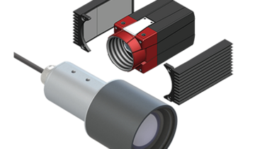
The Alvium camera housing range consists of two accessory kits rather than a standalone camera model. Product code 18534 is the D55 housing, typically used with compact S-Mount lenses, while product code 18535 is the larger D80 version for typical C-Mount and CS-Mount configurations. Both kits support Alvium G1 and G5 cameras and are rated to IP66 and IP67 under IEC 60529. Aluminium camera and lens tubes form the enclosure, with an anti-reflective BK7 glass window providing the optical path.
An included desiccant bag absorbs moisture to help prevent condensation during temperature changes. The housings support machine-vision systems that require environmental sealing, subject to appropriate thermal, mechanical and optical validation. Engineers should check the complete lens envelope, cable diameters, heat-transfer arrangement and mounting torque before specifying either version.
Range features
A high level overview of what this range offers
- IP66 and IP67 classification – Supports installations requiring defined dust and water ingress protection.
- Alvium G1 and G5 compatibility – Uses a housing format designed for the supported camera series.
- D55 and D80 lens envelopes – Provides a choice between a compact tube and a larger internal lens space.
- Aluminium camera and lens tubes – Form the enclosure and support conductive heat transfer to the mounting base.
- BK7 glass window with AR coating – Provides a protected optical path with anti-reflective treatment.
- Desiccant bag and adhesive pad – Absorb moisture to reduce condensation during temperature changes.
- Split and integrated M25 × 1.5 cable entries – Accommodate specified 3.5 mm, 5 mm and 6 mm cable diameters.
- Shock and vibration testing – Provides defined IEC 60068-2-6 and IEC 60068-2-27 test conditions.
- Four M6 mounting threads – Allow top or bottom mounting with specified engagement and torque values.
Downloads
for Alvium camera housings
What’s in this range?
All the variants in the range and a comparison of what they offer
Specifications
| Specification | Range value |
|---|---|
Product type | Camera and lens housing kits |
Product codes | 18534 D55; 18535 D80 |
Ingress protection | IP66 and IP67 |
Ingress protection standard | IEC 60529 |
Supported camera series | Alvium G1 and Alvium G5 |
Camera and lens tube material | Aluminium |
Window material | BK7 glass |
Window treatment | AR anti-reflective coating |
External mounting threads | Four M6 threads, 7.0 mm deep; two on top and two on the bottom |
Split cable entry | M25 × 1.5 with 5 mm and 6 mm cable inserts |
Integrated cable entry | M25 × 1.5 with a 3.5 mm insert or 5 mm and 6 mm inserts |
GigE cable allowance | Maximum diameter of 6 mm |
Optional I/O cable allowance | Maximum diameter of 5 mm |
Dynamic lens condition | Maximum mass of 70 g with a 14 mm centre of gravity from the lens-mount front flange |
Static lens condition | Maximum mass of 250 g with a 50 mm centre of gravity, provided there is no vibration |
Base mounting torque | Maximum 6.6 Nm with 6.5 mm thread engagement; 5.1 Nm with 5.0 mm engagement |
Thermal integration | Additional heat dissipation can be required above 25°C, particularly at high resolution and frame rate |
Main kit components | Camera tube, lens tube, mounting ring, back plate, cable entry, seal rings, screws, desiccant bag and adhesive pad |
Items supplied separately | Camera, lens, cables and M6 mounting-base screws |
Variant comparison
| Specification | 18534 Alvium IP Housing D55 Kit | 18535 Alvium IP Housing D80 Kit |
|---|---|---|
Typical lens configuration | S-Mount | C-Mount and CS-Mount |
Overall diameter × length, including cable entry | 55.0 mm × ≤137.4 mm | 80.0 mm × ≤183.7 mm |
Complete kit mass | 450 g | 600 g |
Internal lens-tube diameter | Ø47 mm | Ø72 mm |
Available length for C-Mount lens | 7.5 mm | 52 mm |
Available length for CS-Mount lens | 12.5 mm | 57 mm |
Available length for S-Mount lens | 12.5 mm | 57 mm |
The available lens lengths exclude the length of the lens mounting thread.
Environmental test conditions
| Test | Parameter | Value |
|---|---|---|
Sinusoidal vibration | Standard | IEC 60068-2-6 |
Sinusoidal vibration | Frequency range | 10 Hz to 58.1 Hz |
Sinusoidal vibration | Displacement | 1.5 mm |
Sinusoidal vibration | Frequency range | 58.1 Hz to 500 Hz |
Sinusoidal vibration | Acceleration | 20 g |
Sinusoidal vibration | Axes | x, y and z |
Sinusoidal vibration | Sweep rate | 1 octave per minute |
Sinusoidal vibration | Sweep duration | 9 hours per axis |
Sinusoidal vibration | Number of sweeps | 20 |
Shock | Standard | IEC 60068-2-27 |
Shock | Acceleration | 40 g |
Shock | Number of shocks | 5,000 per axis |
Shock | Duration | 6 ms |
Shock | Waveform | Half-sine |
Lens dummy | Length and mass | 22 mm and 70 g |
Lens dummy | Centre of gravity | 14 mm from the lens-mount front flange |
FAQs
for Alvium camera housings
Choose the D55 for short, narrow lens assemblies and the D80 where the lens needs more diameter or axial clearance. The D55 provides a Ø47 mm internal diameter and 7.5 mm for C-Mount or 12.5 mm for CS-Mount and S-Mount lenses, so it is typically paired with compact S-Mount optics. The D80 increases the internal diameter to Ø72 mm and provides 52 mm for C-Mount or 57 mm for CS-Mount and S-Mount lenses. These usable lengths exclude the lens mounting thread, and lenses that extend while focusing must be checked at their longest position. Select the kit only after comparing the full lens envelope, including adjustment rings, against these limits.
The completed housing is specified to IP66 and IP67 under IEC 60529 when all sealing components are installed correctly. This depends on using every seal ring, selecting the appropriate cable insert, closing unused cable holes and fully joining the camera and lens tubes. A missing, damaged or displaced seal means the enclosure should not be treated as meeting its stated ingress class. Cable diameter is also part of the sealing arrangement, with inserts provided for 3.5 mm, 5 mm and 6 mm cables depending on the entry type. A controlled assembly and inspection procedure should therefore be established before the housing is installed in the application.
Thermal performance must be validated as part of the complete system because the housing is not a standalone cooling device. If ambient temperature exceeds 25°C, additional heat dissipation may be required, particularly when the camera operates at high resolution and frame rate; the camera can switch off two seconds after its mainboard temperature exceeds its permitted maximum. Mount the aluminium housing to a base with high thermal conductivity, and consider ventilation, shading or software-based temperature monitoring. Thermally conductive gap fillers or graphite foam gaskets can be placed between the camera sides and the housing wall to improve conduction. Field testing should reproduce the intended ambient temperature, solar load, acquisition settings and mounting arrangement.
The housings were evaluated using sinusoidal vibration under IEC 60068-2-6 and shock under IEC 60068-2-27. Vibration testing covered 10 Hz to 58.1 Hz at 1.5 mm displacement and 58.1 Hz to 500 Hz at 20 g acceleration. Testing was conducted on the x, y and z axes at one octave per minute, with nine hours per axis and 20 sweeps. Shock testing applied 40 g, 5,000 times per axis, using a 6 ms half-sine waveform. The test assembly used a 70 g, 22 mm lens dummy with its centre of gravity 14 mm from the lens-mount flange. No housing deformation, loose connections, functional deviation or image-streaming error was reported under these conditions.
For dynamic applications, the lens should not exceed 70 g, with its centre of gravity no more than 14 mm from the lens-mount front flange. This condition corresponds to the lens arrangement used during the shock and vibration tests. For a fully static installation with no vibration, a lens mass of up to 250 g is permitted with a centre of gravity of 50 mm. Mass and centre of gravity must be considered together because a longer lever arm increases the load on the camera mounting points. The selected lens must also remain within the D55 or D80 internal diameter and available-length limits throughout its complete focus range.
The split M25 × 1.5 cable entry is configured for 5 mm and 6 mm cable diameters and is used for the GigE cable arrangement. The integrated M25 × 1.5 entry can use a 3.5 mm insert or inserts for 5 mm and 6 mm cables. The GigE interface cable must have a maximum diameter of 6 mm, while an optional I/O cable must not exceed 5 mm. Any unused opening in a split insert must be closed with the corresponding 5 mm or 6 mm sealing bolt. During assembly, the split-entry double nipple has a maximum torque of 6 Nm and its pressure screw has a maximum torque of 4 Nm.
The housing provides four M6 mounting threads, with two on the top and two on the bottom of the camera tube. A maximum torque of 6.6 Nm applies when the M6 screws have 6.5 mm of thread engagement; this reduces to 5.1 Nm at 5.0 mm engagement and should be scaled proportionally for other permitted engagement lengths. Threadlocker should be applied to the external mounting screws to reduce the risk of loosening. Inside the housing, the four M2 × 4 mm camera screws are limited to 0.18 Nm, the M3 × 6 mm mounting-ring screws to 0.6 Nm and the M3 × 8 mm back-plate screws to 0.8 Nm. Torque values must be adjusted where the actual thread and locking conditions differ from the stated dry-thread conditions.
Install the desiccant bag on its adhesive pad immediately before closing the housing so that it can absorb moisture trapped inside. This is particularly important where the camera will experience temperature changes that could otherwise produce condensation on the lens or internal surfaces. The front window is BK7 glass with an anti-reflective coating, but it should still be protected from scratches because direct light can make window damage visible as flare. Check the lens at every relevant focus setting to ensure that an extending front element cannot contact the window. Assembly and servicing should take place in a clean, dry area, with the sensor protected by a lens or mount cap whenever possible.
Related product ranges
Fujinon SX800 Very Long Range Multi-Purpose Camera
The SX800 40× optical zoom camera covers focal lengths from 20 to 800 mm for long-distance surveillance, monitoring and remote visual inspection. It combines selectable image stabilisation, day/night and infrared operation, atmospheric correction functions, and IP, HD-SDI, HDMI and composite interfaces.