12:1/ 8:1 Input Range DC/DC
- Technology
- DC-DC power supplies
- Partner
- P-DUKE
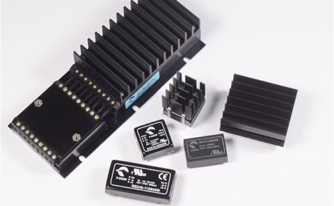
This application-focused range combines eleven active DC/DC converter series rather than representing one configurable product family. It is intended for railway and transport equipment operating from battery systems with substantial variation between nominal, start-up, interruption and surge conditions. Available power ratings extend from 10 W to 200 W, with single and dual outputs covering voltages from 3.3 VDC to 53 VDC. Designers can select compact 1 × 1-inch and 2 × 1-inch modules, quarter-brick and half-brick formats, or enclosed chassis and DIN-rail versions. Depending on the selected series, functions include remote control, output adjustment, external undervoltage lockout configuration, remote sense and hold-up support. The available series address EN 50155 railway applications and include options designed around interruption, changeover, EMC and thermal-management requirements.
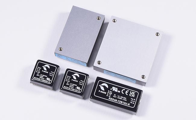
This range groups eleven active railway DC/DC converter series for designers who need to cover wide battery variation, interruption events and installation constraints with application-specific modules rather than a single configurable platform.
Available solutions span compact PCB-mounted converters, quarter-brick and half-brick modules, enclosed chassis styles and DIN-rail options. Across the range, output choices cover low-voltage logic rails through higher-voltage auxiliary supplies, while selected families add hold-up support, remote on/off, output trim, remote sense or configurable undervoltage lockout.
Range features
A high level overview of what this range offers
- Input ranges from 9–75 VDC to 14–160 VDC – Can reduce the number of converter variants required across different railway battery systems.
- Power ratings from 10 W to 200 W – Supports auxiliary control electronics, communications equipment and higher-power onboard loads.
- Single and dual output versions – Accommodates common logic, control, analogue and communications supply rails.
- Up to 3,000 VDC or 3,000 VAC isolation – Provides galvanic separation between the railway battery input and powered circuitry.
- Board, brick, chassis and DIN-rail packages – Allows the mechanical format to be matched to the enclosure and cooling arrangement.
- EN 50155 and EN 45545-2 series options – Supports railway electrical and fire-behaviour design requirements.
- Hold-up and bus-pin arrangements on selected families – Can support continuity during short input interruptions and supply changeover events.
- Remote on/off and output adjustment options – Provides control over sequencing, shutdown and final rail voltage.
- Heat-sink and baseplate configurations – Help designers establish a defined thermal path at higher output powers.
- Overvoltage, overload, short-circuit and thermal protection – Supports controlled behaviour during electrical and thermal fault conditions.
Downloads
for 12:1/ 8:1 Input Range DC/DC
What’s in this range?
All the variants in the range and a comparison of what they offer
| Series | Power (W) | Vin (V) | Vout (VDC) | Isolation | Package | Status |
|---|---|---|---|---|---|---|
RCD10U | 10 | 9-75, 14-160 | 3.3, 5, 5.1, 12, 15, 24, ±5, ±12, ±15 | 3000 VDC | 1×1 inch | Active |
URCD10U | 10 | 14-160 | 3.3, 5, 12, 15, 24, ±5, ±12, ±15 | 3000 VDC | 3.3×2.25 inch | Active |
URCD20U | 20 | 14-160 | 5, 12, 15, 24, ±12, ±15 | 3000 VDC | 3.3×2.25 inch | Active |
RCD20U | 20 | 9-75, 14-160 | 5, 5.1, 12, 15, 24, ±12, ±15 | 3000 VDC | 1×1 inch | Active |
RED40U | 40 | 9-75, 14-160 | 5, 5.1, 12, 15, 24, ±12, ±15 | 3000 VDC | 2×1 inch | Active |
URED40U | 40 | 14.4-160 | 5, 12, 15, 24, ±12, ±15 | 3000 VDC | 4×2.28 inch | Active |
QAE40U | 40 | 9-75, 14-160 | 5, 12, 15, 24, 28, 48, 53 | 3000 VAC/ 2250 VDC | 1/4 Brick | Active |
QAE60U | 60 | 9-75, 14-160 | 5, 12, 15, 24, 28, 48, 53 | 3000 VAC/ 2250 VDC | 1/4 Brick | Active |
QAE100U | 100 | 9-75, 14-160 | 5, 12, 15, 24, 28, 48, 53 | 3000 VAC/ 2250 VDC | 1/4 Brick | Active |
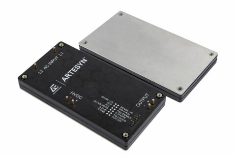
HAE150U | 150 | 16-160 | 5, 12, 15, 24, 28, 48, 53 | 3000 VAC | 1/2 Brick | Active |
HAE200U | 200 | 16-160 | 5, 12, 15, 24, 28, 48, 53 | 3000 VAC | 1/2 Brick | Active |
FAQs
for 12:1/ 8:1 Input Range DC/DC
The input window should be selected against the complete battery profile rather than only its nominal voltage. The 9–75 VDC families suit designs that must accommodate lower railway battery systems, while the 14–160 VDC and 14.4–160 VDC families extend coverage to higher nominal voltages. HAE150U and HAE200U operate from 16–160 VDC continuously and tolerate 12–185 VDC transiently. Start-up and shutdown thresholds, surge limits and the required EN 50155 interruption class must also be considered. These factors determine whether one converter can be standardised across several battery systems or whether separate input variants are necessary.
Begin with the continuous load, conversion losses and expected transient demand, then select a package that provides a practical thermal path. RCD10U and RCD20U offer 10 W and 20 W respectively in a compact 1 × 1-inch footprint, while RED40U provides 40 W in a 2 × 1-inch module. QAE40U, QAE60U and QAE100U use the quarter-brick format, and HAE150U and HAE200U use the half-brick format for higher-power systems. URCD and URED versions provide enclosed mounting alternatives. Available airflow, baseplate temperature, heat-sink space and cable termination requirements should therefore be assessed before choosing solely by wattage.
The required approach depends on whether an integrated or externally configured hold-up arrangement is preferred. URCD10U, URCD20U and URED40U support EN 50155 Class S2 interruption for 10 ms, with 20 ms Class S3 versions available as an option. Selected board-mounted RCD, RED and QAE configurations provide bus or hold-up connections that allow external capacitance to store the required energy. The capacitor value must be calculated at minimum input voltage and maximum load, taking converter efficiency and permitted output decay into account. Hold-up curves and inrush behaviour should be checked for the exact model before fixing the capacitor bank and protection components.
The RCD, RED, URCD and URED families provide 3,000 VDC input-to-output isolation, while the QAE and HAE families include ratings up to 3,000 VAC. Within the QAE range, the exact rating depends on the selected input variant, with reinforced and basic insulation ratings differentiated by model. The series also address EN 50155 and EN 45545-2 requirements, together with IEC, EN and UL 62368-1 safety provisions where specified. These ratings support separation between the battery supply and downstream circuitry. They do not remove the need to verify system-level insulation coordination, earthing, spacing and accessible-voltage requirements for the final installation.
Single-output options extend from 3.3 VDC to 53 VDC, while selected lower-power families also provide ±5 VDC, ±12 VDC or ±15 VDC dual outputs. The dual-output models can suit analogue interfaces and bipolar signal-conditioning circuits, but their cross-regulation should be checked when the positive and negative rails are unevenly loaded. Many single-output variants permit external voltage adjustment, with the available range depending on series and nominal output. HAE150U and HAE200U additionally provide remote-sense capability for compensating distribution losses. Engineers should evaluate output current, capacitive load, ripple, adjustment range and wiring voltage drop together rather than selecting only by nominal voltage.
Thermal performance must be verified at the lowest operating input voltage, maximum load and highest expected enclosure temperature. Most board-mounted and baseplate-cooled series are specified for operation from −40°C to +105°C with derating, while the enclosed URCD and URED units extend to +100°C. The applicable limit may refer to ambient, case or baseplate temperature, so the measurement point is important. Optional heat sinks and conductive baseplate mounting reduce thermal impedance on selected RED, QAE and HAE models. A prototype should be tested in its final mounting orientation and airflow condition to confirm that the relevant case or baseplate limit is not exceeded.
External component requirements vary by series, input range and target EMC class. Where a module is not internally fused, an appropriately rated input line fuse must be installed, while the enclosed URCD and URED models incorporate specified slow-blow input fuses. Meeting EN 55032 and EN 50121-3-2 emission or surge levels may require input capacitors, transient-voltage suppressors and filtering components around the converter. Available internal protections include overvoltage, overload, short-circuit and overtemperature functions, but these protect the converter rather than the complete power distribution network. The final input network should therefore be designed and tested with the exact converter model, source impedance and cable arrangement.