XTBF500 AC/DC Power Supplies
- Technology
- Open / u-frame power supplies
- Partner
- P-DUKE
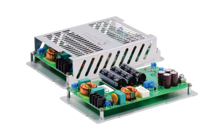
The XTBF500 series is a 500W AC/DC power supply range offered in open-frame and enclosed formats for equipment that requires a single regulated DC rail. It accepts 85 to 264VAC or 88 to 370VDC and provides nominal outputs of 12, 15, 24, 28, 48 or 54VDC. The range integrates input filtering, inrush-current limiting, bulk capacitance and a conductive aluminium base, reducing the number of peripheral power components required around the conversion stage. Conduction cooling supports the full 500W rating under defined thermal conditions, while derating curves are provided for natural convection and 400 LFM forced-air cooling. Open-frame and enclosed versions are available with optional active-droop current sharing for systems that need parallel operation. Remote on/off, remote sense and an open-collector power-good signal support supervisory control within industrial equipment. Typical applications include 5G communications, industrial printing, energy storage systems, robotics, factory automation and defence equipment. The series also addresses railway-oriented requirements through EN 50155 and EN 45545-2 approvals, alongside IEC, EN and UL 62368-1 safety compliance.
Range features
A high level overview of what this range offers
- 500W conduction-cooled output – Supports power-intensive industrial and communications loads under the defined thermal conditions.
- 85 to 264VAC universal input – Allows one supply configuration to operate across common regional mains systems.
- 88 to 370VDC input capability – Supports applications supplied from a suitable high-voltage DC bus.
- Six output-voltage options – Provides 12, 15, 24, 28, 48 and 54VDC choices for different system architectures.
- Up to 93% efficiency – Limits conversion losses and the associated thermal load at rated operating conditions.
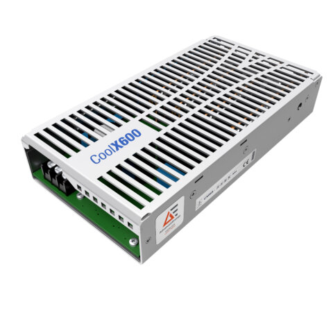
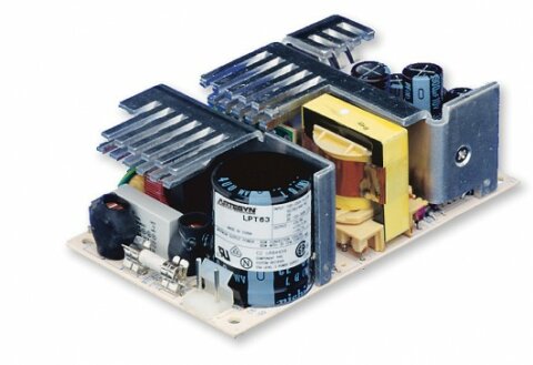
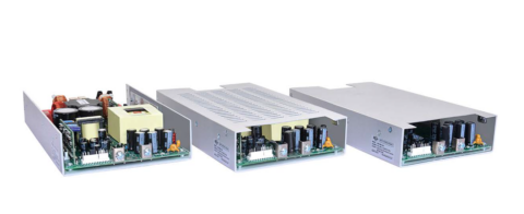
- Open-frame and enclosed packages – Allows selection according to mechanical layout and internal guarding requirements.
- Optional active-droop current sharing – Enables compatible units to be connected in parallel where additional output current is required.
- 0.8W no-load input power at 230VAC – Reduces idle consumption when the connected equipment is not drawing output power.
- Remote sense and remote on/off – Supports cable-drop compensation and external power sequencing.
- Power-good signal – Provides an open-collector status output for system monitoring.
- Overload, short-circuit, overvoltage and overtemperature protection – Defines controlled responses to common electrical and thermal faults.
- 3000VAC reinforced input-to-output insulation – Provides isolation between the mains input and regulated output.
- OVC III and 5000m operating altitude – Supports installations with elevated transient and altitude requirements, subject to system-level validation.
What’s in this range?
All the variants in the range and a comparison of what they offer
| Model | Power (W) | Vin (V) | Vout (VDC) | Isolation | Status |
|---|---|---|---|---|---|
XTBF500US28-S | 500 | 85 ~ 264 | 28 | 3000 VAC | Active |
XTBF500US12-E1 | 500 | 85 ~ 264 | 12 | 3000 VAC | Active |
XTBF500US28-E1 | 500 | 85 ~ 264 | 28 | 3000 VAC | Active |
XTBF500US24 | 500 | 85 ~ 264 | 24 | 3000 VAC | Active |
XTBF500US12-E1S | 500 | 85 ~ 264 | 12 | 3000 VAC | Active |
XTBF500US28-E1S | 500 | 85 ~ 264 | 28 | 3000 VAC | Active |
XTBF500US54 | 500 | 85 ~ 264 | 54 | 3000 VAC | Active |
XTBF500US24-S | 500 | 85 ~ 264 | 24 | 3000 VAC | Active |
XTBF500US54-S | 500 | 85 ~ 264 | 54 | 3000 VAC | Active |
XTBF500US24-E1 | 500 | 85 ~ 264 | 24 | 3000 VAC | Active |
XTBF500US15 | 500 | 85 ~ 264 | 15 | 3000 VAC | Active |
XTBF500US54-E1 | 500 | 85 ~ 264 | 54 | 3000 VAC | Active |
XTBF500US48 | 500 | 85 ~ 264 | 48 | 3000 VAC | Active |
XTBF500US24-E1S | 500 | 85 ~ 264 | 24 | 3000 VAC | Active |
XTBF500US54-E1S | 500 | 85 ~ 264 | 54 | 3000 VAC | Active |
XTBF500US15-S | 500 | 85 ~ 264 | 15 | 3000 VAC | Active |
XTBF500US48-S | 500 | 85 ~ 264 | 48 | 3000 VAC | Active |
XTBF500US15-E1 | 500 | 85 ~ 264 | 15 | 3000 VAC | Active |
XTBF500US12 | 500 | 85 ~ 264 | 12 | 3000 VAC | Active |
XTBF500US48-E1 | 500 | 85 ~ 264 | 48 | 3000 VAC | Active |
XTBF500US28 | 500 | 85 ~ 264 | 28 | 3000 VAC | Active |
XTBF500US15-E1S | 500 | 85 ~ 264 | 15 | 3000 VAC | Active |
XTBF500US48-E1S | 500 | 85 ~ 264 | 48 | 3000 VAC | Active |
XTBF500US12-S | 500 | 85 ~ 264 | 12 | 3000 VAC | Active |
FAQs
for XTBF500 AC/DC Power Supplies
Choose the output voltage first, then select the package and current-sharing suffix. The six electrical versions are 12V/42A, 15V/33.5A, 24V/21A, 28V/18A, 48V/10.5A and 54V/9.4A, each with a 500W rating under the stated cooling conditions. An unsuffixed part is open-frame without load sharing; -S adds load sharing, -E1 denotes the enclosed package, and -E1S combines the enclosure and sharing function. This structure allows the same basic electrical platform to cover single-unit and parallel architectures. The connected load should also remain within the model-specific maximum capacitive-load limit.
The 500W rating requires conduction cooling and should not be treated as an unrestricted free-air rating. The thermal curves use a 482.6 × 222.2 × 2mm plate, with the conduction-cooled curve maintaining full load to approximately 30°C at 115VAC and 40°C at 230VAC before derating towards zero output at 100°C. Natural convection permits a lower percentage of rated output, while 400 LFM airflow extends the full-load temperature range. The final enclosure, mounting plate and surrounding heat sources will affect the operating result. A system-level thermal test should therefore confirm baseplate temperature and output derating under the worst input, load and ambient conditions.
Parallel operation is supported only by models carrying the -S suffix. These versions use active-droop current sharing, with a stated droop rate of 4% from no load to full load and a load-share accuracy of 20% at full load. Their output-adjustment range is limited to ±5%, compared with ±10% for versions without current sharing. Parallel units should use closely matched output wiring so that cable resistance does not create additional current imbalance. The total system design must also coordinate fault protection, remote-sense connections and thermal derating for every supply rather than assuming exact equal sharing.
The supply accepts 85 to 264VAC at 47 to 63Hz and can also operate from 88 to 370VDC. It is classified for OVC III and provides 3000VAC reinforced isolation between input and output, with 2000VAC isolation from input or output to functional earth. The listed standards include IEC, EN and UL 62368-1, EN 50155 and EN 45545-2, together with EN 50121 railway EMC requirements. Conducted emissions are Class B and radiated emissions are Class A under the stated test framework. Equipment-level approval still depends on wiring, earthing, enclosure construction, external protection and the conditions used in the final installation.
The response depends on the type of fault. Overload protection operates at 140% of the maximum rated output current and uses hiccup behaviour, while continuous short-circuit protection automatically attempts recovery after the fault is removed. Output overvoltage protection activates between 115% and 135% of nominal voltage and latches, so the input supply must be cycled or otherwise reset before operation resumes. Overtemperature protection operates at 115°C and recovers automatically after cooling. The host controller should distinguish between recoverable hiccup events and a latched overvoltage shutdown when defining alarms and restart procedures.
Remote sense can compensate for a voltage drop of up to 10% of the nominal output, but the total adjusted output must remain within the permitted range for the selected model. If remote sense is unused, the positive and negative sense pins should be connected to their corresponding output terminals. The remote-control input requires an external supply: 0 to 0.8VDC or an open circuit commands output on, while 4.5 to 12.5VDC commands output off. The control input current is 20mA. The power-good output is referenced to -Vout and uses an open-collector arrangement, so the monitoring circuit must provide an appropriate pull-up.
The permitted capacitive load falls as the output voltage increases, ranging from 16,000μF on the 12V model to 470μF on the 48V and 54V models. Ripple-and-noise limits also vary by model, from 200mVp-p at 12V and 15V to 540mVp-p at 54V, measured with a 20MHz bandwidth and the specified ceramic capacitor. For a 50% to 75% load step at 2.5A/μs, the peak deviation is 3% and recovery to within 1% takes 600μs. Additional downstream capacitance must remain within the relevant model limit. Cable inductance, load slew rate and local decoupling should be reproduced during validation testing.
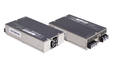
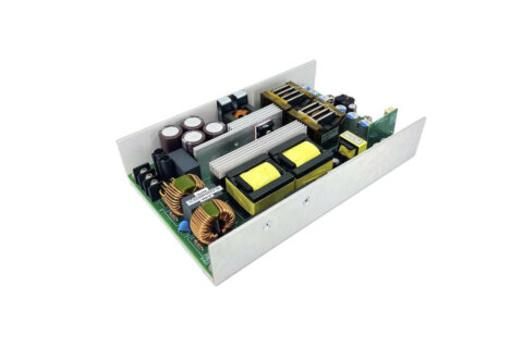
Both formats occupy a 182.9 × 109.2mm footprint, but the open-frame version is 38.0mm high and weighs 580g, while the enclosed version is 42.0mm high and weighs 710g. Four M4 mounting positions are provided, with a maximum mounting-screw torque of 1.02N·m. Input and output power connections use ring terminals, with maximum connection torques of 0.8N·m at the input and 1.65N·m at the output. The enclosed model places a cover over the internal circuitry, although no ingress-protection rating is declared. Clearance for ventilation, cabling and access to the voltage adjustment should be included in the mechanical design.