CHM150 Series – 150Watts 18-36VDC 2:1 Input Half Brick Medical DC-DC Converter
- Technology
- DC-DC power supplies
- Partner
- Cincon
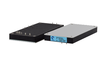
The CHM150 series is a 150 W isolated medical DC-DC converter designed for half-brick power architectures. It accepts an 18–36 VDC input centred on 24 VDC systems and provides regulated 12 V, 15 V or 24 V single outputs. The series is intended for medical equipment, distributed power systems, telecommunications, battery-powered equipment and industrial electronics. Medical integration is supported by 5000 VAC input-to-output isolation, IEC/UL 60601-1 third-edition 2 MOPP approval and a design intended for CF-rated applications. Positive and negative remote on/off variants are available to suit different control schemes. Remote sensing and external output-voltage adjustment support point-of-load accuracy and system flexibility. Protection functions include UVLO, overcurrent, overvoltage, overtemperature and continuous short-circuit protection. Thermal integration is supported by an aluminium baseplate and optional heatsink arrangements across a case-temperature range of −40°C to +100°C.
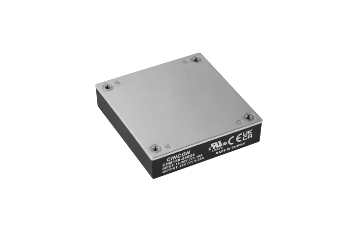
The CHM150 series is a medically approved isolated DC-DC converter family for 24 VDC-centred systems. It combines a standard half-brick footprint with 150 W output power, reinforced 5000 VAC isolation and single-output options of 12 V, 15 V or 24 V.
The range is designed for medical equipment and other demanding embedded platforms where controlled leakage current, 2 MOPP isolation and flexible integration features are required. Positive-logic and negative-logic remote on/off versions, remote sensing, output trim and multiple protection functions support use in complex power architectures.
Range features
A high level overview of what this range offers
- 150 W regulated single output – Delivers a stable power platform for embedded medical and industrial systems.
- 18–36 VDC 2:1 input range – Suited to equipment built around a nominal 24 VDC supply.
- 12 V, 15 V and 24 V output options – Helps match the converter to different load rails.
- Efficiency up to 91.5% – Supports lower power dissipation under rated conditions.
- 5000 VAC input-to-output isolation – Provides reinforced isolation for medical power designs.
- IEC/UL 60601-1 third-edition 2 MOPP approval – Supports integration into medical electrical equipment.
- Design intended for CF-rated applications – Addresses low-leakage requirements in medical systems.
- Touch current up to 10 µA – Supports controlled leakage-current design targets.
- Positive or negative remote on/off logic – Allows different system control strategies.
- Remote sensing up to +10% – Compensates for voltage drop at the load connection.
- Output adjustment from −20% to +10% – Enables output tailoring within the permitted limits.
- Comprehensive protection set – Includes UVLO, OCP, OVP, OTP and continuous short-circuit protection.
- −40°C to +100°C operating case temperature – Supports use across demanding thermal conditions with correct derating.
- 5000 m operating altitude – Suitable for elevated-location equipment subject to system-level assessment.
- 200 kHz nominal switching frequency – Helps with predictable filter and EMC design.
Downloads
for CHM150 Series - 150Watts 18-36VDC 2:1 Input Half Brick Medical DC-DC Converter
What’s in this range?
All the variants in the range and a comparison of what they offer
| Specification | CHM150-24S12 | CHM150-24S15 | CHM150-24S24 | CHM150-24S12N | CHM150-24S15N | CHM150-24S24N |
|---|---|---|---|---|---|---|
Input voltage | 18–36 VDC | 18–36 VDC | 18–36 VDC | 18–36 VDC | 18–36 VDC | 18–36 VDC |
Nominal input voltage | 24 VDC | 24 VDC | 24 VDC | 24 VDC | 24 VDC | 24 VDC |
Output voltage | 12 VDC | 15 VDC | 24 VDC | 12 VDC | 15 VDC | 24 VDC |
Maximum output current | 12.5 A | 10.0 A | 6.25 A | 12.5 A | 10.0 A | 6.25 A |
Rated output power | 150 W | 150 W | 150 W | 150 W | 150 W | 150 W |
No-load input current at 24 VDC | 10 mA | 10 mA | 10 mA | 10 mA | 10 mA | 10 mA |
Full-load input current at 24 VDC | 6831 mA | 6831 mA | 6868 mA | 6831 mA | 6831 mA | 6868 mA |
Efficiency at 24 VDC and full load | 91.5% | 91.5% | 91% | 91.5% | 91.5% | 91% |
Maximum external capacitive load | 20,000 µF | 15,400 µF | 6250 µF | 20,000 µF | 15,400 µF | 6250 µF |
Remote on/off logic | Positive | Positive | Positive | Negative | Negative | Negative |
Input-to-output isolation | 5000 VAC | 5000 VAC | 5000 VAC | 5000 VAC | 5000 VAC | 5000 VAC |
Package | Half-brick | Half-brick | Half-brick | Half-brick | Half-brick | Half-brick |
| Parameter | Specification |
|---|---|
Continuous input-voltage absolute maximum | −0.3 to 36 VDC |
Input surge voltage | 50 VDC maximum for 100 ms |
Maximum input current | 8 A at 22 VDC and full load, or at 18 VDC and 80% load |
UVLO turn-on threshold | 15.6 V minimum, 16.5 V typical, 17.5 V maximum |
UVLO turn-off threshold | 14.6 V minimum, 15.5 V typical, 16.5 V maximum |
UVLO hysteresis | 1 V typical |
Input filter | Pi filter |
Reflected input ripple current | 30 mA peak-to-peak through a 12 µH inductor, 5 Hz to 20 MHz |
Output-voltage set-point accuracy | ±1% |
Load regulation | ±0.2%, full load to no load |
Line regulation | ±0.2%, high line to low line at full load |
Temperature coefficient | ±0.02%/°C |
Peak-to-peak ripple and noise | 150 mV for 12 V and 15 V models; 240 mV for 24 V models |
RMS ripple and noise | 60 mV for 12 V and 15 V models; 100 mV for 24 V models |
Overcurrent protection | 110% minimum, 140% typical, 160% maximum; hiccup mode with automatic recovery |
Short-circuit protection | Continuous with automatic recovery |
Overvoltage protection | 115% minimum, 125% typical, 140% maximum of nominal output voltage |
Output-voltage trim range | −20% to +10% |
Remote-sense range | Up to +10% of nominal output voltage |
Transient error band | ±5% for a 75% to 100% maximum-current load step |
Transient recovery time | 250 µs |
Remote-control turn-on delay | 1.5 ms |
Input power-up delay | 3 ms |
Output-voltage rise time | 10 ms from 10% to 90% of set voltage |
Input-to-output isolation | 5000 VAC for one minute |
Input-to-case isolation | 2500 VAC for one minute |
Output-to-case isolation | 2500 VAC for one minute |
Isolation resistance | 1000 MΩ |
Isolation capacitance | 80 pF typical at 100 kHz and 0.25 V |
Touch current | 10 µA maximum |
Input-to-output creepage | 8 mm |
Input-to-output clearance | 8 mm |
Switching frequency | 185 kHz minimum, 200 kHz typical, 215 kHz maximum |
Positive-logic control | Low or 0–1.2 V turns the module off; high, open or 3.5–36 V turns it on |
Negative-logic control | Low or 0–1.2 V turns the module on; high, open or 3.5–36 V turns it off |
Shutdown input current | 1.5 mA typical, 3 mA maximum |
Overtemperature shutdown | 105°C at the centre of the baseplate; non-latching |
Overtemperature recovery | 88°C |
Operating case temperature | −40°C to +100°C with applicable derating |
Storage temperature | −55°C to +125°C |
Humidity | 95% RH maximum, non-condensing |
Operating altitude | 5000 m |
Transport altitude | 12,000 m |
MTBF at full load and 25°C | 1.346 million hours for 12 V; 1.391 million hours for 15 V; 1.725 million hours for 24 V |
Weight | 128 g |
Case material | DAP plastic, UL 94V-0 |
Baseplate material | Aluminium |
Potting material | UL 94V-0 |
Pin material | Copper with nickel and matte-tin plating |
Safety standards | IEC 60601-1 and ANSI/AAMI ES 60601-1; IEC/UL 60601-1 third-edition 2 MOPP approval |
Shock, vibration and thermal shock | MIL-STD-810F |
EMI standards | EN 60601-1-2, EN 55032, EN/IEC 61204-3, FCC Part 15B, EN/IEC 61000-6-4 and ICES-003 Issue 7 with an external Class A filter |
EMS standards | EN 55035, EN/IEC 61204-3, EN/IEC 61000-6-1, EN/IEC 61000-6-2 and EN 60601-1-2 Edition 4.1 |
FAQs
for CHM150 Series – 150Watts 18-36VDC 2:1 Input Half Brick Medical DC-DC Converter
The series is available with regulated 12 VDC, 15 VDC and 24 VDC single outputs. The corresponding maximum output currents are 12.5 A, 10 A and 6.25 A, with a rated output power of 150 W for each model.
Models without the N suffix use positive remote on/off logic. N-suffix models use negative logic, so the module is off when the remote-control pin is open or held high and on when the pin is pulled low.
The electrical design provides 2 MOPP, 5000 VAC input-to-output isolation and touch current up to 10 µA, and it is intended for CF-rated applications. Compliance of the complete medical device must still be assessed in the final power architecture, enclosure, wiring and applied-part configuration.
Cooling depends on input voltage, output load, ambient temperature, airflow and whether a heatsink is fitted. The case temperature measured at the centre of the aluminium baseplate must remain at or below 100°C, and the relevant derating curves should be applied during system design.
Yes. The trim function allows adjustment from −20% to +10% of nominal output voltage using an external resistor or potentiometer. The resulting output power must remain within the 150 W rating and maximum output-current limit.
The positive and negative sense connections can compensate for voltage drop by up to 10% of nominal output voltage. Twisted-pair or shielded wiring is recommended, and sense wiring longer than 400 mm may introduce instability depending on wiring impedance and load conditions. If remote sensing is not used, each sense pin should be connected locally to its corresponding output terminal.
Direct parallel operation is not supported. Series operation and redundant arrangements are possible when the specified external inductors, capacitors, diodes and current limits are observed.
Yes. There is no internal input fuse, and a 15 A time-delay fuse is recommended for all models. A transient-voltage suppressor and suitable input capacitance are also recommended where protection against surge, fast-transient and reverse-input conditions is required.
Yes. The stated emission and immunity performance requires the external filtering and protection circuits defined for the selected output model. EMC testing should be repeated in the final PCB, enclosure and cable configuration.
Ripple and noise are characterised with 10 µF and 1 µF ceramic capacitors connected across the output. Low-ESR capacitors placed close to the load can also support transient response, provided the model-specific maximum capacitive load is not exceeded.