74000 series flyback switch-mode transformers
- Technology
- Switch-mode transformers
- Partner
- Myrra
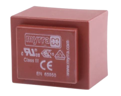
The Myrra 74000 series flyback transformers are designed for engineers creating isolated AC/DC power supplies based on flyback topology. The range spans from low-power 1 W designs up to 180 W, making it suitable for applications from IoT devices to industrial converters. Each transformer uses a high-frequency ferrite core and is pre-engineered to align with popular controller ICs, reducing development effort and avoiding fully custom magnetics. Models are available with single or multiple secondary outputs, and selected versions include auxiliary windings for controller bias supply. Common output voltages include 5 V, 12 V, 24 V and other standard DC rails. The series is built with UL94-V0 listed materials and designed for reinforced insulation to support demanding safety requirements. With compact construction, wide power coverage, and standardised options, the 74000 series offers a practical and cost-effective solution for isolated mains-powered SMPS designs.
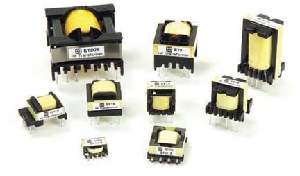
The Myrra 74000 series flyback transformers are standard high-frequency magnetic components for isolated switch-mode power supplies. They are intended for off-line AC/DC converter designs and support a broad range of output power, output configurations, and core sizes.
This range helps simplify SMPS development by giving designers access to pre-engineered transformers with reinforced insulation, compact PCB mounting formats, and options for single-output, multi-output, and auxiliary winding configurations.
Range features
A high level overview of what this range offers
- High isolation design: Primary-to-secondary insulation rated at ≥ 4000 V supports safe galvanic isolation in mains-connected power supplies.
- Reinforced creepage distances: Designed with ≥ 6 mm creepage between primary and secondary windings to support international insulation requirements.
- High temperature operation: Suitable for ambient temperatures up to 120 °C for demanding thermal environments.
- UL Class B insulation system: Uses UL94-V0 flame-retardant materials with a Class B (130 °C) insulation system for long-term reliability.
- Auxiliary winding options: Available with or without an auxiliary winding for controller bias supply flexibility.
- Single or multiple outputs: Supports one or multiple isolated output rails, with up to five outputs in selected models.
- Primary shield availability: Selected versions include a primary-side shield winding to help reduce EMI.
- Wide power range: Standard models cover approximately 1 W to 180 W across the series.
- Standards-oriented design: Developed for reinforced insulation applications in line with IEC safety expectations for mains-powered equipment.
- Fast customisation: Modified-standard and custom versions are available for application-specific requirements.
What’s in this range?
All the variants in the range and a comparison of what they offer
Model(s) | Core size | Max output power (W) | Number of outputs | Output voltages (V DC) |
74004 – 74005 | E16-H (horizontal) | 1.7 | 1 | 4 – 7 / 8 – 12 |
74090 – 74093 | E16-V (vertical) | 1.5 – 3.1 | 1 | 3.3 – 6 / 7.5 – 15 |
74000 | E16-V (vertical) | 5 | 2 | 3.3 – 7 / 8.0 – 17.0 |
74001 – 74002 – 74003 | E16-V (vertical) | 6 | 1 – 2 | 2 – 4 / 3 – 6 / 9 – 18 |
74094 – 74095 | E16-V (vertical) | 9 | 1 | 3.3 – 6 / 7.5 – 15 |
74010 – 74014 – 74015 | E16-V (vertical) | 12 | 2 – 3 | 3.3 – 7 / 4 – 6 / 8 – 17 / 12 – 18 / 15 – 30 / 19.2 – 28 |
74020 – 74021 – 74023 | EL19 | 16 – 18 | 2 and 5 | 3.3 – 7 / 8 – 16.5 / 2.8 – 3.8 / 4.25 – 5.75 / 10.2 – 13.8 / 15.3 – 20.7 / 25.5 – 34.5 |
74087 – 74089 | EF20 | 20 – 24 | 2 – 3 | 2.8 – 3.8 / 4.25 – 5.75 / 3 – 7.5 / 9 – 15 / 10.2 – 13.8 / 15 – 30 |
74030 | E25 | 30 | 3 | 3.3 – 7 / 8 – 16 |
74040 | ETD29 | 60 | 4 | 3.3 – 7 / 8 – 16.5 |
74043 | ERL28 | 60 | 5 | 2.8 – 3.8 / 4.25 – 5.75 / 10.2 – 13.8 / 15.3 – 20.7 / 25.5 – 34.5 |
74050 – 74060 | ETD34 – ETD39 | 90 – 140 | 4 | 3.3 – 6.5 / 8.5 – 17 |
74070 | ETD44 | 180 | 4 | 3.3 – 6.5 / 8.5 – 17 |
- Power coverage: From approximately 1 W to 180 W across the full range.
- Output formats: Available as single-output and multi-output transformers, including versions with up to 5 outputs.
- Mounting options: Includes horizontal and vertical E16 variants depending on model.
- Core families used: E16, EL19, EF20, E25, ETD29, ERL28, ETD34, ETD39 and ETD44.
- Design note: E16-H and E16-V indicate horizontal and vertical mounting orientation for E16 core variants.
FAQs
for 74000 series flyback switch-mode transformers
Yes. The 74000 series is designed for wide-range AC mains input of approximately 85–265 V AC. These transformers provide the isolation needed for off-line flyback converters and are intended for use with common PWM controller ICs in universal-input SMPS designs.
The range is designed for reinforced insulation applications in line with IEC 61558-2-16, with related relevance to standards such as IEC 60950 and IEC 60335. The transformers provide at least 4 kV primary-to-secondary dielectric strength, ≥ 6 mm creepage distances, UL94 V-0 materials, and a UL Class B insulation system.
An auxiliary winding can be used to power the primary-side controller or provide a bias supply. If your SMPS controller requires its own supply rail, selecting a version with an auxiliary winding can simplify the design. If your controller is self-powered or another bias source is available, a version without the auxiliary winding may be sufficient.
Start by defining the required output power, output voltage combination, and number of isolated outputs. Then choose a transformer model that meets or exceeds the needed power level and matches the output configuration. You should also verify compatibility with your controller IC, switching frequency, and primary inductance requirements using the series documentation and datasheets.
The 74000 series uses a wide range of ferrite core styles to support different power levels. Lower-power models use E16 cores in horizontal or vertical formats, mid-range models use EL19, EF20, or E25, and higher-power versions use ETD29, ERL28, ETD34, ETD39, and ETD44 cores.
Yes. Selected models include a primary shield winding that helps reduce capacitive coupling of high-frequency noise from primary to secondary. Correct transformer sizing also helps reduce saturation and leakage-related issues. Final EMI performance will still depend on the full power supply design, PCB layout, and filtering.
Yes. In addition to the standard catalogue range, modified-standard and fully custom versions can be developed for specific voltage combinations, form factors, or electrical requirements. This can help reduce time to market when a standard part is close to, but not exactly, the target specification.
Using a standard transformer series can shorten development time and reduce design risk. These parts offer known magnetic, thermal, and safety characteristics and are intended to work with mainstream flyback controller ICs. That lets engineers focus on the wider power supply design while retaining the option for later customisation if needed.