SDS05W / SDH05W 5W Isolated DC/DC Converters
- Technology
- DC to high voltage DC conversion power supplies
- Partner
- P-DUKE
The SDS05W/SDH05W series is a family of 5 W isolated DC-DC converters designed for demanding industrial, telecom, and instrumentation applications. Each module accepts a wide 4:1 input range (with variants for 9–36 V or 18–75 V DC inputs), making it compatible with standard 12 V, 24 V, or 48 V supply systems and battery-powered equipment. The series offers a choice of surface-mount (SMD8) and through-hole (DIP8) packaging – allowing engineers to select either a reflow-solderable module for high-density boards or a DIP module for prototyping and legacy designs. Despite their miniature size (about 13.2 × 9.1 × 10.2 mm), these converters provide reinforced isolation (1600 V DC, with optional 3000 V DC versions) to protect sensitive circuitry and break ground loops.
They deliver fully regulated outputs in a range of voltages (including ±dual outputs for bipolar supply needs), with no minimum load required for stable operation. Integrated short-circuit protection and compliance with IEC/UL/EN 62368-1 safety standards ensure that the SDS05W/SDH05W modules can be deployed confidently in critical systems ranging from wireless networking gear and telecom base stations to industrial control devices and test/measurement equipment. The result is a flexible, robust power solution that can simplify isolated power design across a wide spectrum of applications.
Range features
A high level overview of what this range offers
- Ultra-compact SMD8 and DIP8 package (13.2 × 9.1 × 10.2 mm) – Minimises PCB space usage and supports high-density layouts; available in surface-mount or through-hole format for design flexibility.
- 4:1 wide input voltage range (9–36 V or 18–75 V) – Enables one converter to handle multiple supply scenarios (e.g. both 12 V and 24 V sources), accommodating large input fluctuations (battery discharge, transients) with ease.
- No minimum load required – Maintains stable, regulated output even at zero-load conditions, improving system efficiency during standby or light-load operation and simplifying design (no dummy load needed).
- Continuous short-circuit protection – Protects both the converter and the load during fault conditions by limiting output current into a short; the module automatically recovers normal operation when the fault is removed, enhancing reliability.
- High isolation voltage (1600 V DC standard, 3000 V DC option) – Provides robust galvanic isolation between input and output, improving safety and noise immunity. This is ideal for breaking ground loops and protecting downstream circuits in high-voltage or noisy environments.
- Safety certified & RoHS compliant – Designed to meet IEC/UL/EN 62368-1 safety standards, which eases end-product certification. The converters are CE marked and compliant with RoHS II and REACH directives, ensuring they meet global safety and environmental requirements.
- Remote On/Off control – Includes a remote control pin to enable or disable the output on demand. This feature allows power sequencing and intelligent power management (e.g. turning off the converter to save energy when a subsystem is not in use).
- Reflow-solderable SMD version – The SDS05W SMD8 modules are qualified for lead-free reflow soldering processes (per IPC J-STD-020D), making them compatible with standard automated assembly. The SDH05W DIP8 versions offer a pin-through-hole alternative for traditional mounting or socket use.
What’s in this range?
All the variants in the range and a comparison of what they offer
Models with 9–36 V input (SDS05-24xxxx and SDH05-24xxxx variants):
Model (9–36 V in) | Output (V DC) | Max Output Current (mA) | No-Load Current (mA) | Efficiency (typ.) | Max Capacitive Load (µF) |
SDS05-24S3P3W / SDH05-24S3P3W | 3.3 V | 1000 mA | 20 mA | 76% | 4400 µF |
SDS05-24S05W / SDH05-24S05W | 5 V | 1000 mA | 30 mA | 80% | 2200 µF |
SDS05-24S09W / SDH05-24S09W | 9 V | 555 mA | 30 mA | ~82% | 1500 µF (approx.) |
SDS05-24S12W / SDH05-24S12W | 12 V | 420 mA | 30 mA | 83% | 1220 µF |
SDS05-24S15W / SDH05-24S15W | 15 V | 333 mA | 30 mA | 83% | 1000 µF |
SDS05-24S24W / SDH05-24S24W | 24 V | 210 mA | 30 mA | 83% | 470 µF |
SDS05-24D05W / SDH05-24D05W | ±5 V | ±500 mA per rail | 30 mA | 80% | ±1000 µF per rail |
SDS05-24D12W / SDH05-24D12W | ±12 V | ±210 mA per rail | 30 mA | 83% | ±680 µF per rail |
SDS05-24D15W / SDH05-24D15W | ±15 V | ±168 mA per rail | 30 mA | 84% | ±440 µF per rail |
Models with 18–75 V input (SDS05-48xxxx and SDH05-48xxxx variants):
Model (18–75 V in) | Output (V DC) | Max Output Current (mA) | No-Load Current (mA) | Efficiency (typ.) | Max Capacitive Load (µF) |
SDS05-48S3P3W / SDH05-48S3P3W | 3.3 V | 1000 mA | 10 mA | 76% | 4400 µF |
SDS05-48S05W / SDH05-48S05W | 5 V | 1000 mA | 12 mA | 81% | 2200 µF |
SDS05-48S09W / SDH05-48S09W | 9 V | 555 mA | 15 mA | ~83% | 1500 µF (approx.) |
SDS05-48S12W / SDH05-48S12W | 12 V | 420 mA | 15 mA | 83% | 1220 µF |
SDS05-48S15W / SDH05-48S15W | 15 V | 333 mA | 15 mA | 83% | 1000 µF |
SDS05-48S24W / SDH05-48S24W | 24 V | 210 mA | 15 mA | 83% | 470 µF |
SDS05-48D05W / SDH05-48D05W | ±5 V | ±500 mA per rail | 15 mA | 80% | ±1000 µF per rail |
SDS05-48D12W / SDH05-48D12W | ±12 V | ±210 mA per rail | 15 mA | 83% | ±680 µF per rail |
SDS05-48D15W / SDH05-48D15W | ±15 V | ±168 mA per rail | 15 mA | 84% | ±440 µF per rail |
FAQs
for SDS05W / SDH05W 5W Isolated DC/DC Converters
The series comes in two wide-range input categories: one accepts 9 V to 36 V DC and another covers 18 V to 75 V DC. This 4:1 input range means each converter can handle substantial variations or different standard bus voltages (for example, the 9–36 V range covers nominal 12 V and 24 V supplies, while 18–75 V covers 24 V and 48 V systems) without any adjustment.
Single-output models are available for 3.3 V, 5 V, 9 V, 12 V, 15 V, or 24 V DC outputs. Dual-output models provide symmetrical ±5 V, ±12 V, or ±15 V outputs (with a common 0 V). Each converter is rated for about 5 W output power in total. For example, the 5 V single-output version can provide up to 1 A (5 V × 1 A = 5 W). Higher-voltage outputs supply proportionally lower current (e.g. the 24 V model gives ~0.21 A for ~5 W). Dual output units split the 5 W between the positive and negative rails (for instance, ±15 V can deliver roughly 0.17 A on each rail). All outputs are fully regulated, maintaining their set voltage across load and input variations.
No minimum load is required – each SDS05W/SDH05W converter remains stable and within regulation from 0% load up to full load. This is convenient for systems that have very light loads or idle periods, as you won’t need any dummy resistors to meet a load requirement. Additionally, the modules feature continuous short-circuit protection. If the output is shorted or overloaded, the converter will limit the current (or enter a safe-hiccup mode), preventing damage. Once the fault is removed, the converter automatically resumes normal operation.
Standard models provide 1600 V DC isolation between input and output. There are also "H" suffix versions with 3000 V DC isolation for applications that need extra-high isolation. This high isolation helps ensure safety and reduces electrical noise coupling between circuits. In terms of safety standards, the series is tested to meet IEC, UL and EN 62368-1 (the safety standard for IT and AV equipment). The converters are CE marked, and they also comply with RoHS II and REACH directives. All of this means they meet internationally recognised safety and environmental criteria, which can simplify compliance for your end product.
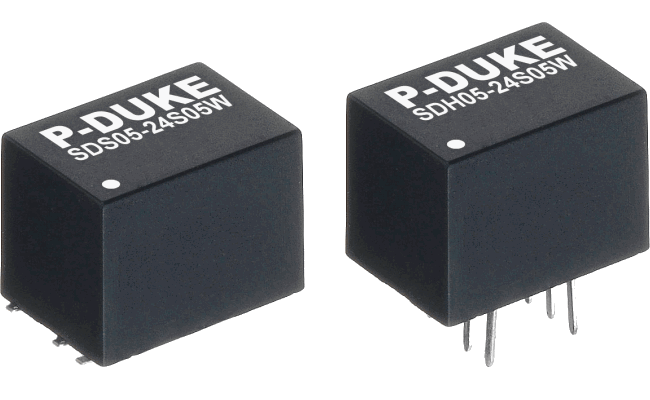
The electrical specifications are identical between SDS05W and SDH05W models of the same variant – the only difference is the package and mounting style. SDS05W modules are in an SMD8 package, designed for surface-mount soldering directly onto the PCB (suitable for reflow soldering). SDH05W modules are in a DIP8 thru-hole package with pins, intended for through-hole mounting (ideal for manual assembly, socket use, or when a taller profile is acceptable). In short, SDS05W is for compact, automated assembly, whereas SDH05W is for traditional or prototyping-friendly assembly. You can choose whichever fits your manufacturing process; performance will be the same.
Yes. Each converter includes a remote on/off control pin (sometimes labeled CTRL or EN) to enable or disable the output on demand. By using this pin, you can enable or disable the converter’s output electronically. For example, pulling the control pin to a specified logic level (refer to the datasheet for the exact polarity and threshold) will turn the output on or off. This feature is very useful for power sequencing (bringing up different supply rails in order) or for power saving — you can shut down the converter when its output isn’t needed, reducing standby power consumption in your system.
The SDS05W/SDH05W converters are quite efficient for their size. Typical efficiency ranges from around 76% (for the 3.3 V output models) up to about 83–84% (for the 12 V, 15 V, and ±15 V models) at full load. The 5 V and 9 V units tend to fall in the ~80–82% range. In terms of temperature, these modules are designed for a broad –40 °C to +85 °C ambient operating range. At higher ambient temperatures or full-power operation, you may need some airflow or derating (check the datasheet’s derating curve), but generally they can handle up to 85 °C without issue. The converters are encapsulated in a thermally efficient plastic case, and their internal design manages heat well for typical conditions.
The SDS05W/SDH05W series is engineered with low EMI in mind, but like most DC-DC converters, you will likely need to add some external components to meet stringent EMC standards (especially EN 55032 Class B for emissions). The manufacturer’s EMC application note provides guidelines: typically, adding an input LC filter (inductors and capacitors) and proper decoupling capacitors on the input/output will significantly attenuate switching noise. Also, maintaining good PCB layout practices – such as short connections, a proper ground plane, and placing filter components close to the module – will help. By following the recommended filter network from the EMC considerations document, these converters can satisfy EMI requirements for most applications.
The output ripple/noise is relatively low for these modules. At full load, you can expect on the order of 50 to 100 mVpp of ripple on the output, depending on the model and conditions. For example, the 5 V output unit typically has around 75 mVpp ripple at nominal input and full load (with the recommended output capacitor in place). Higher-voltage outputs like 12 V or 15 V often show ripple on the lower end of that range (tens of mV). Using a good quality low-ESR output capacitor and following the layout recommendations will ensure the ripple remains low. If needed, you can always add an external LC filter or an additional output capacitor to further smooth the output for especially noise-sensitive analog or RF circuits.