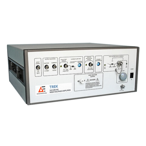
PZD700A-1-H-CE Piezo Driver and High Voltage Amplifier 700 V, 100 mA
- Technology
- High voltage amplifiers and piezo drivers
- Partner
- Trek / Advanced Energy
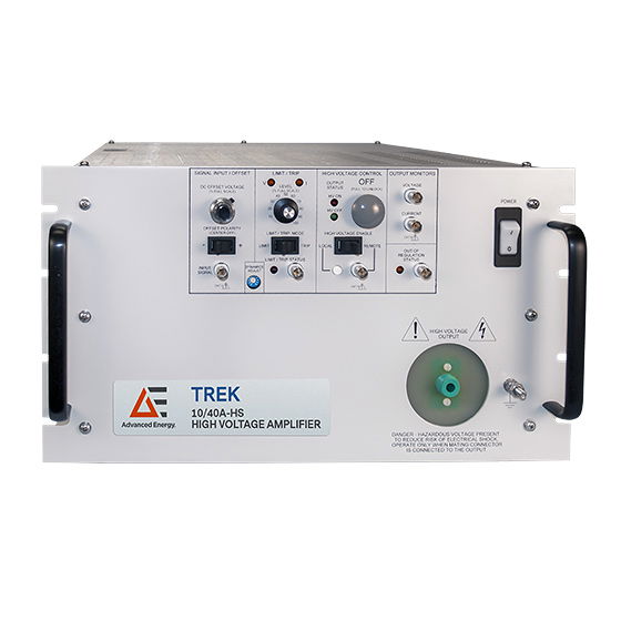
The TREK PZD700A is a DC-stable high voltage piezo driver and amplifier built for precision and speed. It provides up to 0.7 kV output at 0.1 A, making it ideal for driving piezoelectric actuators, electro-optic devices, and other high-voltage components. With a wide bandwidth (up to ~200 kHz small-signal) and fast slew rate, it can reproduce rapid voltage changes and high-frequency waveforms with accuracy. The amplifier’s four-quadrant output stage can both source and sink current, ensuring stable control of reactive loads like capacitors or piezo stacks. Available in bipolar (±350 V) or unipolar (0–700 V) output ranges, the PZD700A suits applications that demand either symmetric bipolar drive or extended unipolar high-voltage output. It comes as a compact benchtop unit (rack-mountable if needed) and includes an adjustable gain up to 300 V/V for flexibility in different control setups.
Range features
A high level overview of what this range offers
- Bipolar or unipolar output ranges – Choose ±700 V for symmetric drive or 0 to 1400 V for one-sided high voltage, allowing optimal matching to your application’s requirements.
- Four-quadrant output stage – Sources and sinks current into reactive loads, enabling reliable driving of capacitive devices (e.g. piezo actuators) without instability or overshoot.
- High slew rate (≈380 V/µs) – Rapid voltage transition capability ensures fast response and reduced settling time, which is crucial for high-speed modulation and precision control tasks.
- Wide bandwidth performance – Large-signal bandwidth over 125 kHz (–3 dB) and small-signal bandwidth over 200 kHz support a broad spectrum of AC waveforms, from slow DC sweeps to high-frequency signals.
- Low-noise, stable output – All-solid-state, closed-loop design with low output noise delivers highly accurate voltages, improving measurement fidelity in sensitive experiments.
- Automatic power limiting – Built-in power limit feature protects the amplifier and load by preventing excessive output power, enhancing safety and reliability during operation.
- User-adjustable gain (0–300 V/V) – Front-panel gain control lets you scale input signals conveniently, making it easy to achieve the desired output voltage range from various signal sources.
- Short-circuit and arc protection – The output is safeguarded against short circuits and voltage arcing events, which helps protect both the amplifier and your connected device from accidental damage.
- Certified calibration – Each unit includes a traceable calibration certificate (e.g. NIST standard), assuring you of accuracy and performance compliance from the moment it’s deployed.
Downloads
for PZD700A-1-H-CE Piezo Driver and High Voltage Amplifier 700 V, 100 mA
What’s in this range?
All the variants in the range and a comparison of what they offer
| Specification | Bipolar Version (±700 V output) | Unipolar Version (1400 V output) |
|---|---|---|
Output Voltage Range | 0 to ±700 V DC or peak AC | 0 to +1400 V or 0 to –1400 V DC or peak AC |
Output Current Range | 0 to ±100 mA | 0 to ±50 mA |
Slew Rate (at rated load) | ≥ 380 V/µs | ≥ 370 V/µs |
Large-Signal Bandwidth (–3 dB) | DC to ≥ 125 kHz | DC to ≥ 120 kHz |
Small-Signal Bandwidth (–3 dB) | DC to ≥ 200 kHz | DC to ≥ 200 kHz |
Gain (DC) | 0 to 300 V/V (adjustable) | 0 to 300 V/V (adjustable) |
Output Power | ~140 W (max into load) | ~140 W (max into load) |
Channels available | Single-channel (PZD700A-1) | Single-channel (factory-set positive or negative output) |
FAQs
for PZD700A-1-H-CE Piezo Driver and High Voltage Amplifier 700 V, 100 mA
The bipolar version of the PZD700A provides a symmetrical output range of ±700 V (i.e. it can drive positive or negative voltages up to 700 V), with a maximum output current of ±100 mA. The unipolar version is configured for a one-sided high voltage output: it can output 0 to +1400 V (or alternatively 0 to –1400 V if ordered for negative polarity) with a maximum current of ±50 mA. In practice, choose the bipolar model if your application requires driving both positive and negative voltages, for example oscillating or bidirectional signals. Choose the unipolar model if you need a higher voltage in one direction only (up to 1.4 kV) and your load current requirements are lower. Both versions share the same bandwidth and general performance characteristics, aside from the voltage and current limits.
The PZD700A is specifically designed to drive capacitive and other reactive loads safely and effectively. It uses a four-quadrant output stage, meaning it can both source and sink current. When driving a capacitive piezo actuator, for instance, the amplifier can source current to charge the actuator quickly and also sink the return current when the actuator discharges or the drive signal is reduced. This design prevents voltage overshoot and ringing, giving stable and controlled response even with highly reactive (capacitive) loads. Additionally, the amplifier’s output is protected against short circuits and voltage spikes (arcs), which can occur in reactive or high-voltage systems, so it can tolerate the sudden energy feedback from such loads without damage.
“Small-signal bandwidth” refers to the frequency range over which the amplifier can reproduce small amplitude signals (typically a few percent of full output) with minimal attenuation (up to the –3 dB point). For the PZD700A, the small-signal bandwidth is over 200 kHz, which means it can follow fast, low-amplitude voltage changes (or high-frequency AC waveforms) up to roughly 200 kHz. “Large-signal bandwidth,” on the other hand, is specified for signals that swing nearly the full output voltage. The PZD700A’s large-signal bandwidth is about 120–125 kHz at the –3 dB point for maximum amplitude signals. In practical terms, if you need to drive a high-voltage output at tens of kHz (for example, a 100 kHz sine wave at hundreds of volts amplitude), the amplifier can achieve this. At frequencies beyond its large-signal bandwidth, the output amplitude will begin to roll off and the waveform may distort. For very small signals, it can handle somewhat higher frequencies, but generally for best fidelity you would operate within the specified bandwidth limits.
The slew rate of the PZD700A is about 380 V/µs (for the bipolar unit, the unipolar is roughly 370 V/µs). Slew rate indicates how fast the amplifier can change its output voltage. For example, 380 V/µs means the output can theoretically swing by 380 volts in one microsecond (under ideal conditions). This high slew rate is important for applications requiring very fast voltage transitions or pulses. A high slew rate ensures that when you apply a fast-changing input (for instance, a square wave or a rapid step voltage), the output can rise or fall quickly without undue delay. In piezoelectric or electro-optic applications, a faster slew rate translates to quicker actuator response, faster settling times, and the ability to drive high-frequency signal components without distortion. In summary, the PZD700A’s fast slew rate enables it to faithfully reproduce rapid waveform changes and sharp pulses up to its bandwidth limits.
The PZD700A acts as a linear power amplifier. You provide an analog input signal (for instance from a function generator or DAC), and the amplifier boosts this signal to a higher voltage at the output. The amplifier’s gain is user-adjustable up to 300 V/V via a front-panel potentiometer (or control interface). For example, if you set a gain of 100 V/V and input a 5 V peak waveform, the output will be 500 V peak. At the maximum gain of 300 V/V, a 2.33 V input would yield approximately 700 V output. This adjustability allows you to fine-tune the amplifier for different input ranges and desired output spans. The input impedance is typically high (to not load your signal source), and the device is DC-coupled, meaning it will amplify static DC inputs as well as AC signals. In summary, you control the output by feeding in a low-voltage signal and setting the appropriate gain; the PZD700A then faithfully amplifies that signal to high voltage.
Yes. The PZD700A is DC-stable, which means it can output a steady DC voltage (up to the maximum of its range) indefinitely. This is useful for applications requiring a fixed high bias voltage. It can also output AC waveforms (sine waves, square waves, arbitrary signals) up to high frequencies (within the bandwidth limits). The amplifier essentially reproduces the shape of your input signal at a much higher voltage level. Because it has a DC-coupled output stage, there is no modulation or minimum frequency – you can go from 0 Hz (DC) to the specified kHz range. Keep in mind that at very high frequencies or very rapid changes, the output amplitude may start to attenuate due to the bandwidth limit, but overall it is capable of driving both slow-changing DC outputs and fast AC transients. This flexibility makes it suitable for a wide range of tasks, from biasing experiments with a stable high voltage to driving dynamic tests and waveforms in materials research or device characterization.
The PZD700A incorporates several protection features to safeguard both itself and your load. First, it has an automatic power limiting circuit that monitors the output and prevents the amplifier from exceeding its safe power output limits – this helps avoid overheating and component stress in case of abnormal load conditions. Second, the output stage is designed to handle short-circuits: if the output is accidentally shorted or the load draws excessive current, the amplifier will limit the current to protect its transistors. Third, in high-voltage applications, “arcing” (a sudden discharge or spark) can occur in the load – the PZD700A’s output is robust against brief arc-down events and will recover without damage. In practice, you may see the amplifier current-limit or shut down momentarily during a direct short or arc, but it will resume normal operation once the fault is cleared. Additionally, each unit is delivered with a calibration certificate and undergoes thorough testing, so you can trust that the protection mechanisms function as specified. Nonetheless, it’s always good practice to operate within the specified limits and use proper high-voltage handling procedures to minimise the chances of triggering these protective features.