Mercury specialty positioner
- Technologie
- Pan- und Neigepositionierer
- Partner
- Quickset Defense Technologies, LLC
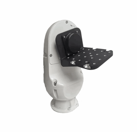
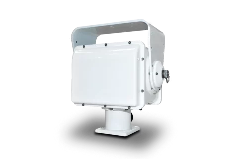
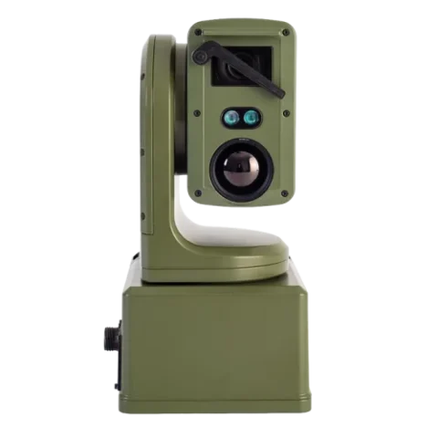
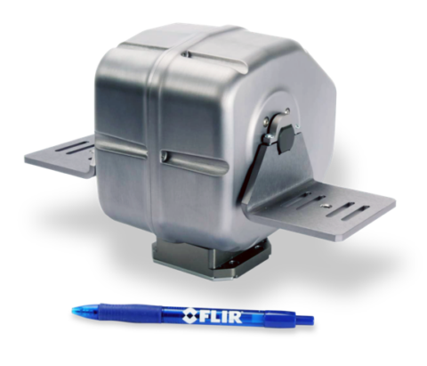
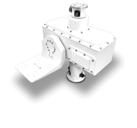
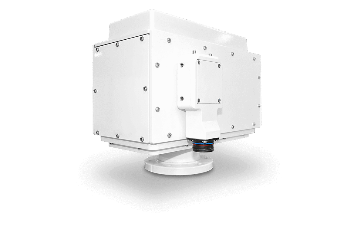
The Mercury HD-SDI pan-and-tilt positioner is a rugged positioning platform for mobile and fixed sensor installations. It carries multiple balanced payloads, including dual-sensor EO/IR configurations used on surveillance poles, towers, boats and ground vehicles. Mobile installations support balanced payloads up to 52 lb, while fixed or stationary installations support up to 75 lb. Both axes provide speeds from 0.005°/s to 100°/s for controlled observation, scanning and rapid repositioning.
A dual-channel HD-SDI slip ring maintains two video paths during continuous pan rotation, and dual GigE pass-through connections are available. IP, RS-232 and RS-422 interfaces provide flexible integration with host control systems and connected payloads. Health and usage monitoring, an embedded web server, IP67 protection and salt/fog provisions support exposed and remotely managed installations.
Eigenschaften
- Balanced payload capacity up to 52 lb mobile or 75 lb fixed: Supports multi-sensor payload assemblies in stationary and vehicle-mounted systems.
- Continuous 360° pan rotation: Allows uninterrupted azimuth movement without a mechanical pan stop.
- 180° tilt range with ±90° travel: Provides coverage above and below the horizontal reference position.
- Axis speeds from 0.005°/s to 100°/s: Accommodates slow observation, scanning and faster target-to-target movement.
- 0.01° position resolution and 0.05° repeatability: Supports consistent pointing and preset positioning.
- Dual-channel HD-SDI slip ring: Maintains two HD-SDI video paths during continuous pan movement.
- Dual GigE pass-through available: Supports network-connected payloads and sensors.
- IP and RS-232/RS-422 control: Simplifies integration with networked and serial control architectures.
- Native PTZ and Pelco-D protocol support: Provides a choice of command interfaces for host-system integration.
- 10-bit linear velocity response: Allows finer control of commanded movement speeds.
- Health and Usage Monitoring System: Supports condition and usage monitoring within the installed system.
- Embedded web server: Provides browser-accessible functions without requiring a separate local interface.
- Multiple payload communication ports: Consolidates four configurable serial links, two TTL connections and one IP connection.
- IP67 and salt/fog environmental provisions: Supports outdoor and exposed installations within the specified operating limits.
Verfügbare Modellvariationen
Alle verfügbaren Varianten und ein Vergleich ihrer Spezifikationen
Specifications table
| Specification | Value |
|---|---|
Mobile load capacity | 52 lb balanced load |
Fixed load capacity | 75 lb balanced load |
Operating voltage | 24–28 V DC; 24 V DC nominal |
Peak operating current | Less than 8.0 A |
Continuous operating current | Less than 6.0 A during simultaneous pan and tilt movement with payloads |
Standby current | Less than 2.1 A |
Pan range | Continuous 360° rotation |
Pan speed | 0.005°/s to 100°/s |
Tilt range | 180° total travel, ±90° |
Tilt speed | 0.005°/s to 100°/s |
Operating temperature | -32°C to +55°C (-25.6°F to +131°F) |
Position resolution | 0.01° |
Repeatability | 0.05° |
Motor and drive | Stepper motor with belt drive |
Positioner communication | IP and serial RS-232/RS-422 |
Serial-over-IP operation | Supported, including a virtual serial connection over one IP link |
Control protocols | Native PTZ protocol and Pelco-D |
Velocity control | 10-bit linear response with direct degrees-per-second commands |
Payload communication ports | Four configurable serial ports, two TTL ports and one IP port |
Video pass-through | Dual-channel HD-SDI |
Additional data pass-through | Dual GigE connections available |
Connector interface | Military-specification 53-contact D38999 connector |
Environmental provisions | IP67; MIL-STD-810 salt/fog; CE |
Monitoring | Health and Usage Monitoring System included |
Web interface | Embedded web server included |
Positioning functions | Geo-positioning and geo-targeting |
Base-unit weight | 52 lb (23.6 kg), excluding payload wings |
Test cable | 6 ft test cable |
Finish options | Flat Black (FB), Marine Grey (MNG), Olive Drab (MOR), Desert Tan (BGP), Marine White (MWS) and CARC Black (CBLK) |
Accessories
| Part number | Description |
|---|---|
CC62131 | Mercury wings and payload interface kit |
CC56545 | 53-socket base cable to flying leads, available in various lengths |
4-65741 | PTU standoff adaptor |
Typical mounting disturbance parameters used for stabilisation analysis
| Mount style | Disturbance frequency | Disturbance amplitude |
|---|---|---|
Surveillance pole | 0.1 Hz | 10° |
Surveillance pole or boat | 0.2 Hz | 10° |
Boat or ground vehicle | 0.5 Hz | 10° |
Ground vehicle | 1.0 Hz | 2° |
The measured results below apply to a stabilised configuration carrying two balanced 35 lb payloads and subjected to a 7.5° platform disturbance.
Measured stabilisation performance for a configured system
| Disturbance frequency | Platform disturbance | Azimuth rejection ratio | Elevation rejection ratio |
|---|---|---|---|
0.05 Hz | 7.5° | 2.14 | 2.59 |
0.10 Hz | 7.5° | 10.00 | 5.77 |
0.20 Hz | 7.5° | 5.36 | 11.54 |
0.34 Hz | 7.5° | 2.08 | 4.41 |
0.50 Hz | 7.5° | 1.42 | 2.34 |
Rejection ratio is the platform angular disturbance divided by the resulting line-of-sight movement. These measurements are specific to the tested payload and control configuration and should not be treated as general performance guarantees.
FAQs
für Mercury specialty positioner
Use 52 lb as the balanced mobile payload limit and 75 lb as the balanced fixed or stationary limit. These figures refer to the total payload carried by the positioner, so sensor housings, brackets and interface hardware should be included in the load calculation. The payload must also be balanced because an allowable centre-of-gravity offset or overturning moment is not defined. The base unit itself weighs 52 lb (23.6 kg) before payload wings, which must be considered when sizing vehicle roofs, masts and support structures. In practice, establish the mounting mode first and then verify total mass, payload balance and structural stiffness.
The positioner provides continuous 360° pan and 180° tilt arranged as ±90°, with both axes operating between 0.005°/s and 100°/s. Position resolution is 0.01°, while repeatability is specified as 0.05°. This range allows the same mechanism to undertake slow observation movements, scanning routines and faster target-to-target repositioning. The continuous pan path incorporates a dual-channel HD-SDI slip ring, avoiding a video-cable restriction on azimuth rotation. Payload clearance should still be checked throughout the full tilt envelope, particularly when wide brackets or multiple sensor housings are fitted.
The required input is 24–28 V DC, with 24 V DC specified as the nominal operating voltage. Current remains below 8.0 A at peak, below 6.0 A during continuous simultaneous pan and tilt movement with payloads, and below 2.1 A in standby. The power source, cable conductors and protection devices should therefore be sized for the peak demand rather than the standby figure. Voltage drop also needs to be assessed where the positioner is installed on a tall mast or connected through a long vehicle cable run. A matching power supply can be requested, but its suitability should be confirmed against the complete payload and cabling arrangement.
The Mercury HD-SDI pan-and-tilt positioner can be controlled through IP or serial RS-232/RS-422 connections, with native PTZ and Pelco-D command support. Serial-over-IP operation and a virtual serial link over a single IP connection allow serial payloads to be incorporated into a networked system. Payload communications include four configurable serial ports, two TTL ports and one IP port, while an embedded web server provides onboard network access. The 10-bit linear velocity response and direct degrees-per-second commands are relevant where host software must generate defined movement profiles. Protocol command coverage, addressing and serial electrical levels should be confirmed during system integration.
Two HD-SDI video channels can pass through the positioner, including across the slip ring used for continuous pan rotation. This arrangement is intended for multi-sensor systems such as dual EO/IR payloads that require more than one video path. Dual GigE pass-through connections are also available for network cameras, encoders or other Ethernet payloads. As GigE is described as an available connection, it should be confirmed as part of the required configuration rather than assumed for every unit. The 53-contact D38999 payload interface and selected base cable must also be checked against the system pin allocation, signal types and required cable length.
The positioner is specified with IP67 protection, MIL-STD-810 salt/fog provisions and an operating range of -32°C to +55°C. These characteristics support use on outdoor surveillance poles, towers, marine platforms and ground vehicles within the stated environmental limits. The complete installation must still account for sealing at external connectors, cable entries and payload interfaces because system-level protection depends on every connected component. Mobile mounting also requires consideration of the 52 lb base-unit mass and the permitted 52 lb balanced payload. Detailed vibration, shock and individual environmental test methods are not defined, so installation-specific qualification may be necessary for demanding platforms.
A stabilised architecture is documented, but stabilisation should be specified explicitly rather than assumed to be standard in every positioner. The configured design uses gyroscopic feedback, a PID control loop, adjustable feedback settings, drift compensation and phase compensation where required. Testing with two balanced 35 lb payloads showed that rejection ratio varied with disturbance frequency and axis; for example, azimuth reached 10.00 at 0.10 Hz, while elevation reached 11.54 at 0.20 Hz. A rejection ratio of 10 means that 7.5° of platform movement would produce approximately 0.75° of line-of-sight movement under comparable conditions. Selection should therefore consider the platform disturbance spectrum, sensor field of view, payload balance and required pointing stability.