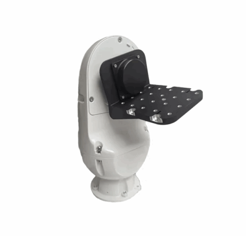
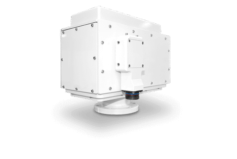
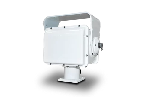
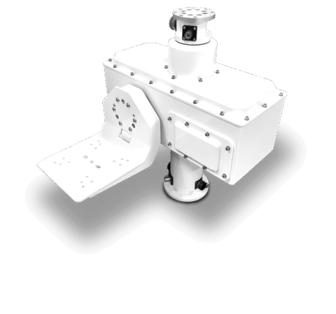
Positionneur spécialisé QPT-RF
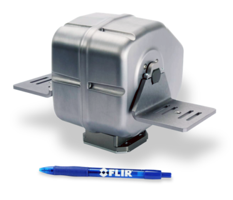
The QPT-RF RF rotary joint pan-and-tilt positioner provides controlled antenna movement for tracking, telemetry and communications systems. QPT-50, QPT-90 and QPT-500 variants accommodate different load moments, supply voltages and axis-speed requirements. An integrated slip-ring arrangement enables continuous pan rotation while routing RF, video, power and control connections through the positioner. Single- and dual-channel RF configurations support frequencies up to 18 GHz.
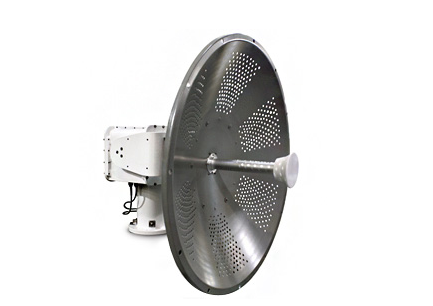
Compatible antenna formats include parabolic, dish, patch and grid designs, ranging from man-portable units to 3-metre antennas. Auxiliary payloads can include visible, NIR, SWIR, MWIR and LWIR imaging devices, illuminators, laser range finders and GPS equipment. Typical applications include UAV tracking and telemetry, satellite communications, radar and other directional RF systems. Serial and Ethernet interfaces support integration with networked and legacy control architectures.
Caractéristiques de la gamme
Un aperçu général de ce que cette gamme offre
- RF rotary-joint pass-through to 18 GHz: Carries antenna signals through the moving assembly.
- Single or dual isolated RF paths: Supports architectures requiring one or two RF channels.
- Continuous pan and 180° tilt travel: Provides wide azimuth and elevation coverage.
- Three load-moment classes: Matches the positioner to complete payload assemblies from 50 to 500 lb-ft.
- Integrated slip ring: Routes RF, video, power and control connections internally during rotation.
- Serial and Ethernet control: Supports legacy and network-based control systems.
- Optical encoder feedback: Provides 0.01° position readout for controlled movement.
- Auxiliary sensor interfaces: Accommodate imaging devices, illuminators and ranging equipment.
- Internal thermostatic heater: Supports operation from -30 to 55°C.
- Adjustable motion limits: Constrain movement to the permitted operating envelope.
Téléchargements
pour Positionneur spécialisé QPT-RF
Qu’est-ce qu’il y a dans cette gamme ?
Toutes les variantes de la gamme et une comparaison de ce qu’elles offrent
Specifications
| Specification | QPT-RF series |
|---|---|
Available variants | QPT-50, QPT-90 and QPT-500 |
Supported antenna formats | Parabolic, dish, patch and grid |
Antenna size range | Man-portable antennas up to 3 metres |
RF configurations | Single channel or dual high-bandwidth channels, depending on variant |
Pan-axis range | Continuous rotation through an integrated slip ring |
Tilt-axis range | 180° (±90°) |
Operating temperature | -30 to 55°C with heater |
Internal heater | Thermostatically controlled; on at 0°C and off at 1.7°C |
Rotational limits | Adjustable tilt hard limit and adjustable soft limits on both axes |
Position feedback | Optical encoders with 0.01° readout |
Motor and drive | Stepper motor |
Positioner communications | RS-232, RS-422, RS-485 and 10/100 Base-T Ethernet |
Sensor communications | RS-232/422, Ethernet pass-through and coaxial video |
Control protocols | PTCR-96 or Pelco D |
Load connector interface | One Mil-Spec-grade connector at the tilt axis |
RF connector | N-Type female, 50 Ohm, rated up to 18 GHz |
Connector construction | Mil-Spec-grade connectors across all configurations |
Materials | 6061-T6 aluminium housing, stainless-steel hardware and permanently sealed radial ball bearings |
Standard finish | White powder coat over a chromate-treated substrate |
Test equipment | 6 ft test cable and software included |
Duty cycle | Periodic movement; constant-motion applications require an application-specific configuration |
Variant Comparison
| Specification | QPT-50 | QPT-90 | QPT-500 |
|---|---|---|---|
Maximum load capacity | 50 lb-ft (67.8 Nm) | 90 lb-ft (122 Nm) | 500 lb-ft (679 Nm) |
Operating voltage | 24 VDC ±4 VDC | 24 VDC ±4 VDC | 48 VDC ±4 VDC |
Supply current | 5.0 A peak; under 0.5 A steady state | 7.5 A peak; under 0.8 A steady state | 6.0 A peak; under 0.8 A steady state |
Pan-axis speed | 0.005° to 50°/s | 0.005° to 25°/s | 0.001° to 20°/s |
Tilt-axis speed | 0.005° to 12°/s at 50 lb-ft | 0.005° to 8°/s at 90 lb-ft | 0.001° to 4°/s |
Pan-and-tilt repeatability | ±0.05° | ±0.05° | ±0.1° |
Weight | 36 lb (16.3 kg) | 70 lb (32 kg) | 175 lb (79 kg) |
RF Channel Configuration Comparison
| RF specification | QPT-50 and QPT-90 single Channel 1 | QPT-50 and QPT-500 dual Channel 1 | QPT-50 and QPT-500 dual Channel 2 |
|---|---|---|---|
Channel configuration | Single channel | Dual high bandwidth | Dual high bandwidth |
Channel identifier | Channel 1 | Channel 1 | Channel 2 |
Frequency range | DC to 18 GHz | DC to 18 GHz | DC to 16 GHz |
Maximum VSWR | 1.5:1 | 1.75:1 | DC–4 GHz: 2:1; 4–8 GHz: 3.25:1; 8–12 GHz: 3.5:1; 12–16 GHz: 5:1 |
VSWR WOW/360 maximum | 0.05 | 0.05 | DC–4 GHz: 1.0; 4–12 GHz: 0.60; 12–16 GHz: 1.50 |
Maximum insertion loss | 0.3 dB | DC–12 GHz: 1 dB; 12–18 GHz: 1.5 dB | DC–4 GHz: 1.0 dB; 4–12 GHz: 2.5 dB; 12–16 GHz: 5.0 dB |
Insertion-loss WOW/360 maximum | 0.1 dB | 0.05 dB | DC–4 GHz: 0.1 dB; 4–12 GHz: 0.6 dB; 12–16 GHz: 1.0 dB |
Minimum isolation | Not applicable | 50 dB between channels | 50 dB between channels |
Peak power | 3 kW | 1 kW for the dual configuration | 1 kW for the dual configuration |
Average power | 500 W at 1 GHz | 30 W | 10 W |
FAQs
pour Positionneur spécialisé QPT-RF
Selection should be based on load moment, required axis speed and available DC supply rather than antenna mass alone. The QPT-50 is rated to 50 lb-ft (67.8 Nm), the QPT-90 to 90 lb-ft (122 Nm), and the QPT-500 to 500 lb-ft (679 Nm). Their maximum pan speeds are 50°/s, 25°/s and 20°/s respectively, while the first two use 24 VDC and the QPT-500 uses 48 VDC, each with a ±4 V tolerance. Calculate the worst-case overturning moment from payload offset, cable forces and environmental loading before choosing a variant. This ensures that the selected unit has suitable mechanical and electrical margin for the complete assembly.
The single-channel configuration is appropriate when one RF path is sufficient and low loss or higher power handling is important. It covers DC to 18 GHz with a maximum VSWR of 1.5:1, maximum insertion loss of 0.3 dB, 3 kW peak power and 500 W average power at 1 GHz. The dual high-bandwidth arrangement provides Channel 1 from DC to 18 GHz and Channel 2 from DC to 16 GHz, with 50 dB minimum isolation and lower average-power limits of 30 W and 10 W respectively. Channel 2 also has frequency-dependent VSWR and insertion-loss limits that rise towards 16 GHz. Use the dual option only after checking transmitter power, receive-path loss budget and acceptable high-frequency mismatch.
The range supports controlled pointing, but the relevant figures must be interpreted separately. Continuous pan rotation and 180° tilt travel provide broad mechanical coverage, while optical encoders offer 0.01° position readout. Repeatability is ±0.05° for QPT-50 and QPT-90 and ±0.1° for QPT-500; this is the figure to use when assessing return-to-position consistency. Speed ranges extend down to 0.005°/s on QPT-50 and QPT-90 and 0.001°/s on QPT-500, supporting slow scan profiles as well as faster repositioning. Overall pointing performance will also depend on mounting stiffness, payload balance, structural deflection and antenna beamwidth.
The positioner can be integrated through serial or Ethernet control without a separate external cable wrap for the moving axes. Pan-and-tilt communications include RS-232, RS-422 and RS-485, plus 10/100 Base-T Ethernet, using PTCR-96 or Pelco D control protocols. Sensor services include RS-232/422, Ethernet pass-through and coaxial video, with one Mil-Spec-grade connector located at the tilt axis for the load interface. The internal pass-through arrangement keeps RF, video, power and control paths within the rotating assembly. Before integration, confirm protocol command support, connector pin assignments, cable shielding, network latency and the power allocation for every attached sensor.
The series can operate from -30 to 55°C when used with the internal heater, which switches on at 0°C and off at 1.7°C. The housing uses 6061-T6 aluminium, stainless-steel hardware and permanently sealed radial ball bearings, with a white powder-coat finish over a chromate-treated substrate as standard. Mil-Spec-grade connectors and adjustable motion limits can support fixed outdoor installations. However, no ingress-protection rating, wind-load rating or icing limit is defined. For exposed sites, verify enclosure sealing, drainage, corrosion compatibility, heater energy, wind-induced load moment and foundation stiffness as part of the system-level design.
The platform can carry auxiliary sensors alongside the antenna, provided the combined load moment and interface requirements remain within the selected variant’s limits. Supported payload types include visible, NIR, SWIR, MWIR and LWIR imaging devices, IR or visible illuminators, laser range finders and GPS equipment. Serial, Ethernet and coaxial video pass-through services can reduce the need for external moving cable loops, while the tilt-axis load connector provides a defined connection point. The mechanical assessment should include sensor offsets, brackets and cable forces, not only nominal sensor mass. The electrical design must also confirm supply demand, data compatibility, RF isolation and connector allocation for the complete payload package.
The standard duty profile is periodic movement, so continuous scanning or uninterrupted tracking should not be assumed without further engineering review. The stated axis-speed ranges describe available motion rates, but they do not define a continuous-duty percentage or thermal endurance limit. A unit may remain installed as part of a round-the-clock surveillance system while moving only when targets or scheduled scans require repositioning. Applications involving constant raster scanning, persistent satellite tracking or repeated high-speed reversals can create higher motor, drive and bearing loads. For those profiles, define the motion cycle, ambient temperature, payload moment and expected service duration before final configuration.